Week -2
SIMULINK MODEL OF DOOR BELL AND THERMISTOR TO SENSE TEMPERATURE
AIM :
To build a simulink model of a door bell using solenoid and also to build a model using thermistor to sense the temperature of a heater and switch the fan off and on under given conditions.
1.FIRST MODEL
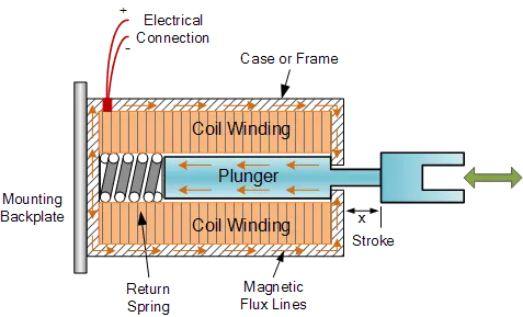
Door bell that to be constructed using simulink based on the model given below
This contains battery, switch,solenoid valve, metal arm.
SOLENOID : This was a mechanical device which works with the moment of the plunger when an electric input is given that input converts into a magnetic field and creates a moment in the plunger.
PROCEDURE :
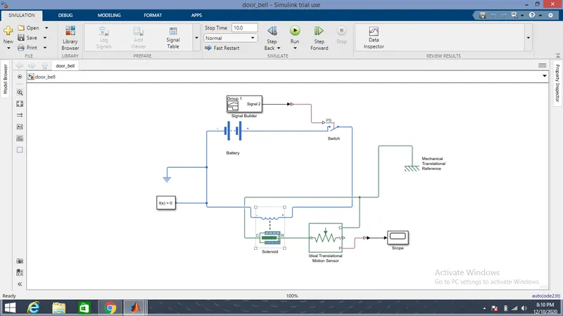
As we are going to connect the blocks the required output will be displayed in the scope block which can be well explained by the below model and explaination.
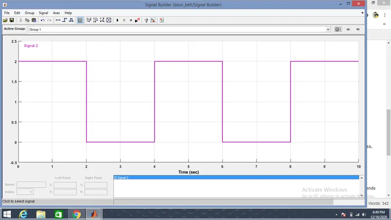
Signal from the signal builder is shown below :
EXPLAINATION :
1. For this model to be constructed we need the following blocks. Battery source, solenoid, electrical reference, mechanical reference, a simple PS switch, PS-Simulink and vice versa, Ideal Translational motion sensor, Signal builder, solver configuration and scope blocks.
2. Then arranging the blocks in which the battery positive terminal goes to switch which has PS signal as input which is connected with signal builder where input signal is given.
3. So in the switch if the threshould value is greater than the given value switch will be closed and if it is less than that switch will be opened.
4. In the input signal builder we have to give the frequency value to get the desired output.
5. So the switch is connected to solenoid valve and then to trenslational motion sensor then, we have to convert this signal from physical to simulink signal by PS-Simulink that extends upto the scope block.
6. Finally in the scope block were are getting the result.
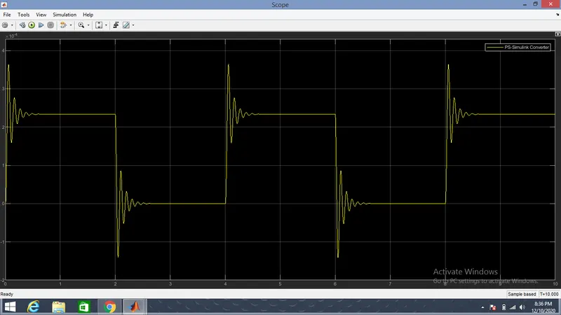
OUTPUT :
So the final graph is obtained between the time and the position of the soenoid and this shows us the result that for the first two second the bell is ringing and for the next two seconds supply from the battery to the switch is stopped and the ringing of the bell will be stopped.
2. SWITCH ON/OFF THE FAN BASED ON TEMPERATURE VARIATION SENSED BY THERMISTOR
THERMISTOR :
Thermistor is a device that alters the resistance in the circuit when temperature is changed which is the input for the thermistor.

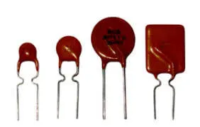
Basically there are two types of thermistors known to be NCT(negative coefficient thermistor) and PCT(Positive coefficient thermistor), where as NCT increases resistance with decrease in the temperature and PCT increases its resistance with increase in the temeprature.
AIM :
The aim of this challange is to build the model that takes input as a temperature and based on this temperature variation the fan should be switched on/off using thermistor.
PROCEDURE :
SIMULINK MODEL EXPLAINATION :
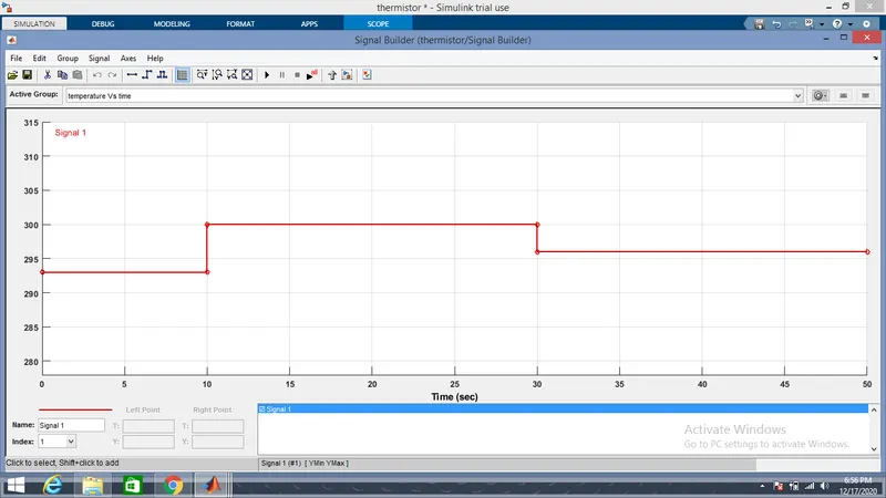
- Firstly a battery source is connected to a thermistor which has a input as a temperature in the form of a signal using signal builder and it is controlled by the controlled temperature source.
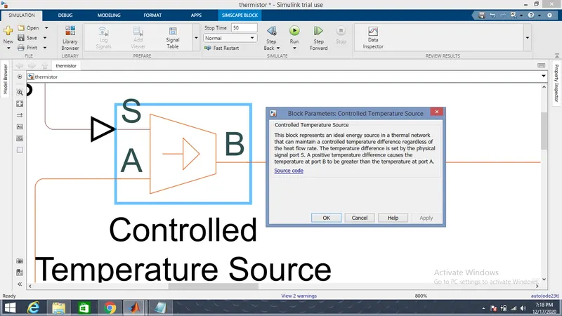
2. So this thermistor is connected in series with the current source and current source is connected to the display block
| Sno. | Time | Temperature |
Fan ON condition Temp >25 = ON |
| 1. | 0-10 | 20 celcius | OFF |
| 2. | 10-30 | 27 celcius | ON |
| 3. | 30-50 | 23 celcius | OFF |
3. So here the condition is if the temperature reaches above 25 celcius the resistance changes and at that point and the current at that point(at change in the resistance) is noted which is allowed to display in the display block.
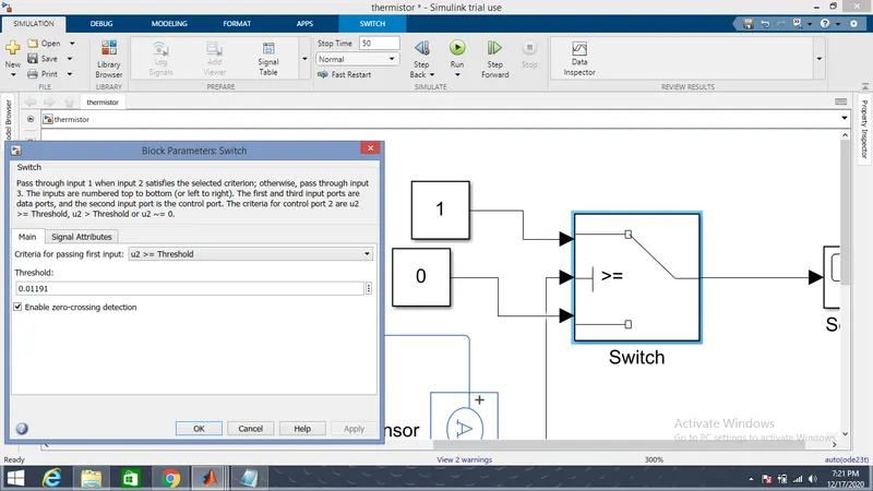
4. This obtained current value is noted and that value is given in the switch block which is called as a condition block used for execute a particular condition.This switch block has a true, condition and a false statements.
5. The solver configuration block is also to be connected in the circuit for solving the simulink model.
6. And also a thermal reference is connected to temperature source, electrical reference is connected to the electrical circuit.
7. At finally scope block is attached to the switch block to obtain the final result.
8. So while running the model the running time is set to 50 sec.
OUTPUT :
From the final output in the scope on the axis is shown that at the temperature above the 25 degree celcius the fan switch is in ON position and the remaining is in the OFF position.
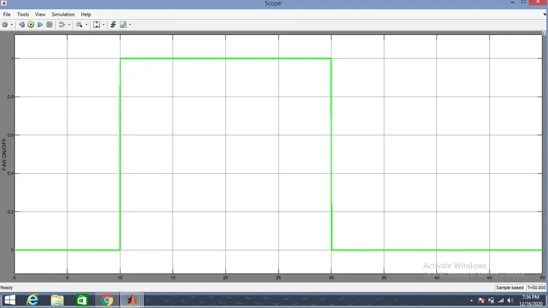
Here x-axis represents time range and the y-axis represents the temperature range.
CONCLUSION :
Therefore in the door bell model in the first two seconds bell has rung and then stopped using solenoid and also in the second model when temperature is reached above 25 degree celcius fan is in ON position.
GOOGLE DRIVE LINK :