Week -2
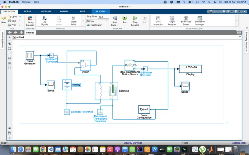
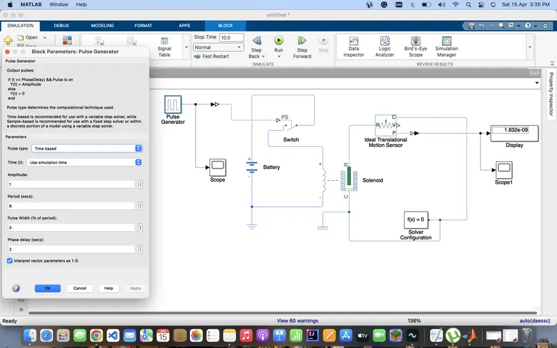
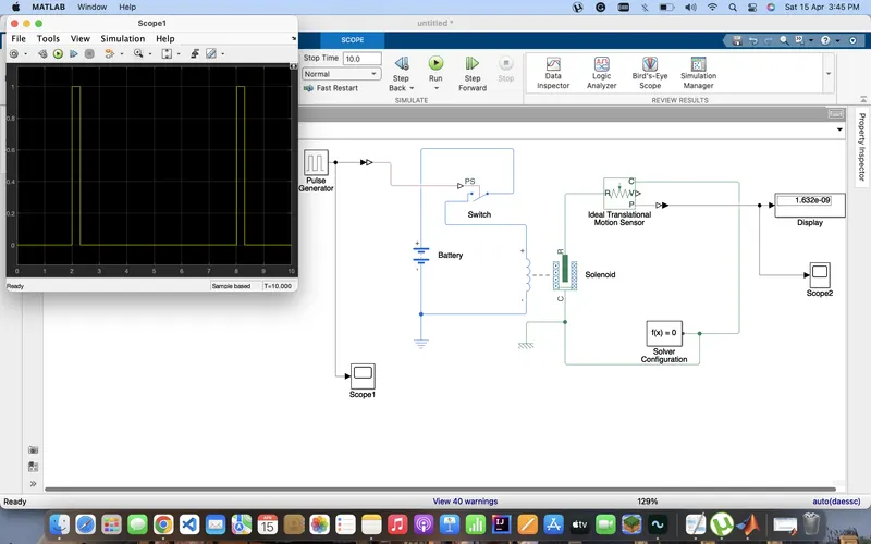
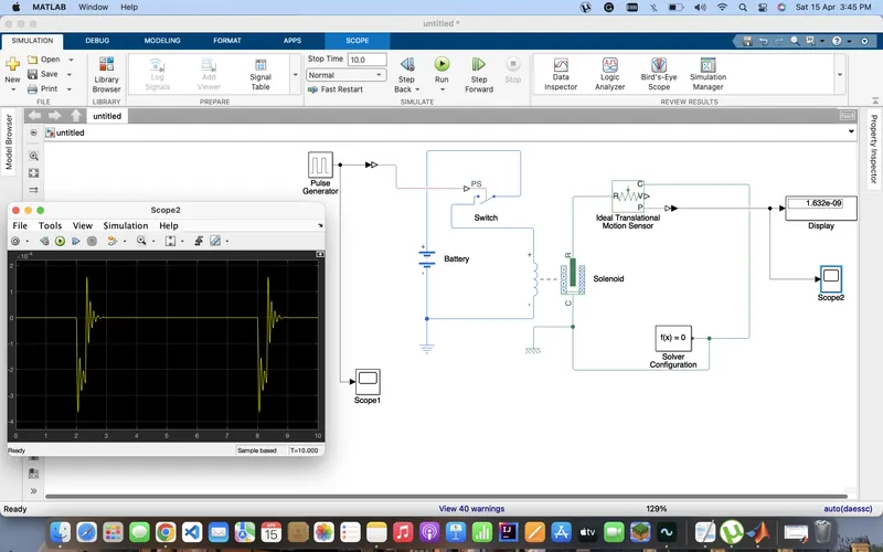
sol.1 Simulink model of Doorbell using solenoid block- simulink model is created to create a sound for the doorbell. here we used solenoid block to create a magnetic field .
1. Battery- this block is used here to supply the power t0 the circuit
2. Switch - the block represents a switch controlled by an external physical signal. If the external physical signal PS is greater than the threshold, then the switch is closed, otherwise the switch is open.
3. Pulse generator- the Pulse Generator block generates square wave pulses at regular intervals. The block waveform parameters, Amplitude, Pulse Width, Period, and Phase delay, determine the shape of the output waveform. The following diagram shows how each parameter affects the waveform.
4. Solenoid- This block measures velocity or displacement in a mechanical translational network. The sensor is ideal since it does not account for inertia, friction, delays, energy consumption, and so on.
5. Ideal translational motion sensor -the ideal translational sensor is connected with a solenoid to observe the motion of the plunger
6. Simulink P-S converter- simulink p-s converter is used to converts the Simulink input signal to a Physical Signal.
7. P-S simulink converter- P-S simulink converter is used to convert the input Physical Signal to a Simulink output signal.
8. Electrical reference- Electrical Reference block represents an electrical ground. Electrical conserving ports of all the blocks that are directly connected to ground must be connected to an Electrical Reference block. A model with electrical elements must contain at least one Electrical Reference block.
9. Mechanical translational reference- The Mechanical Rotational Reference block represents a reference point, or frame, for all mechanical rotational ports. All rotational ports that are rigidly clamped to the frame (ground) must be connected to a Mechanical Rotational Reference block.
10. Solver configuration - All physical network represented by a connected simscape block requires solver setting information for simulation
11. Scope - scope block is used to see the Simulink output
Ques-2
sol-2
Conditions:
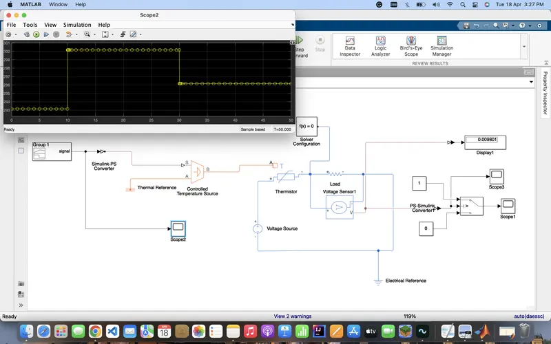
Temperature source: 20 °C from 0 to 10 seconds, 27 °C from 10 to 30 seconds, 23 °C from 30 to 50 seconds.
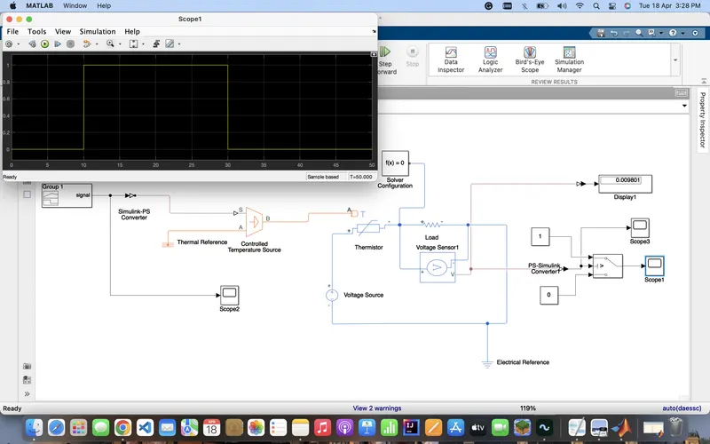
Fan conditions: ON if the temperature is above 25 °C, OFF otherwise.
Blocks used in the model:
- Thermistor
- Signal builder block
- Controlled Temperature Source
- Resistor
- Voltage sensor
- Switch
- Scope
- Display
- PS-Simulink Converter
- Simulink-PS Converter
- Solver Configuration
- Voltage source
- Constant block
- Electrical reference
- Thermal reference
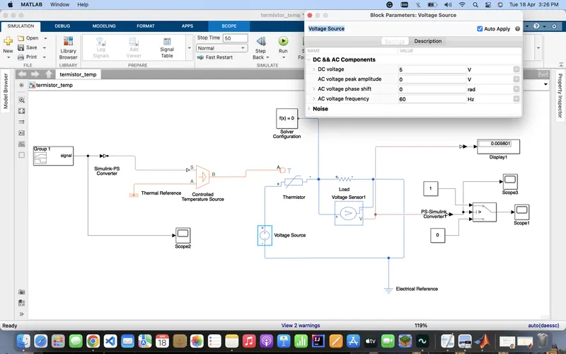
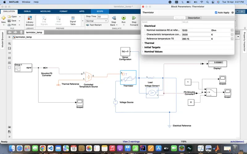
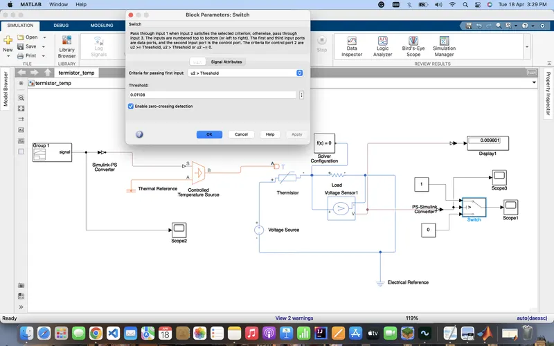
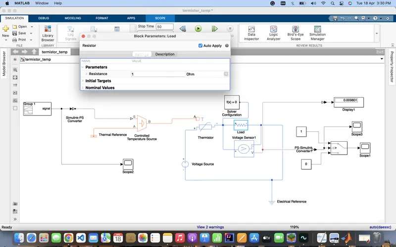
Simulink model
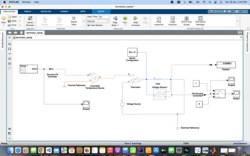
- For Time Set “ 0 to 10 “ seconds, the Temperature is “293.15K”
- For Time Set “10 to 30” seconds, the Temperature is “300.15K”
- For Time Set “30 to 50” seconds, the Temperature is “296.15K”