Week -2
AIM :
- To make a simulink model of Doorbell using solenoid block.
- To Use a thermistor to sense the temperature of a heater & turn on or turn off the fan as per below conditions.
Temperature Source: Temperature source: 20 °C from 0 to 10 seconds, 27 °C from 10 to 30 seconds, 23 °C from 30 to 50 seconds
Fan conditions: ON if the temperature above 25 °C, OFF otherwise.
OBJECTIVE :
- Create a Simulink model of Doorbell using Solenoid Block. Operate the Door bell Simulink model system and plot the results.
- Using a thermistor to sense the temperature of a heater & turn on or turn off the fan as per given conditions.Run the Simulink Model as per given conditions and plot the results.
DOORBELL:
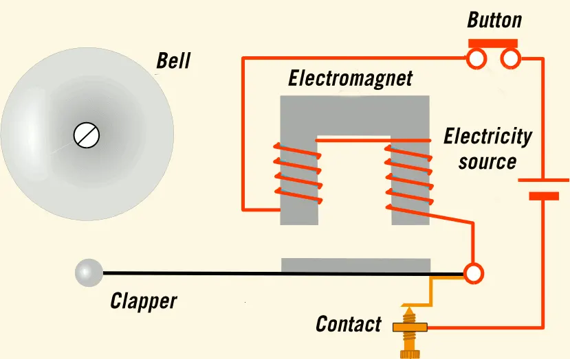
When We Press The Doorbell,This Will Complete a Circuit That Allows Electricity To Flow Through The Doorbell’s Internal Electromagnet. The Magnetic Field Generated By The Electromagnet Is Then Used To Power a Mechanism That Creates The Doorbell Sound. Doorbell Are Low-Voltage Devices.
SOLENOID
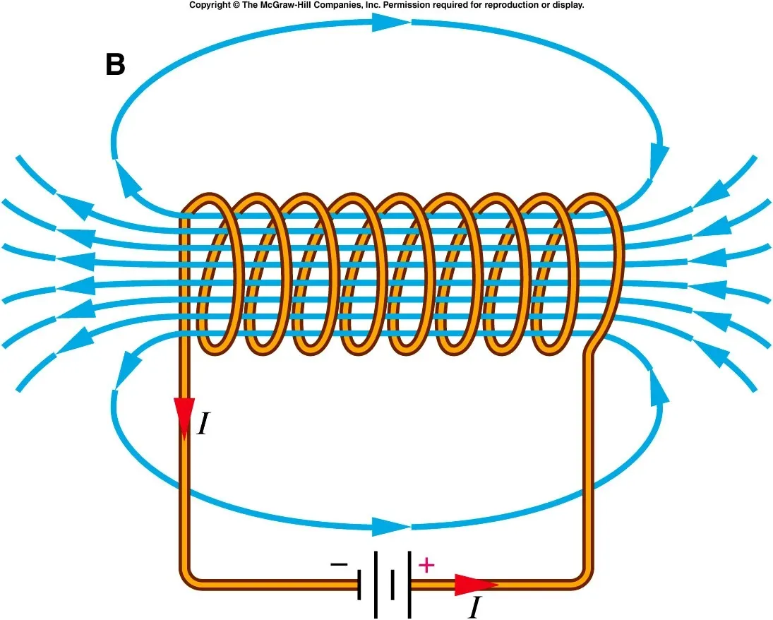
A solenoid is a three dimensional structure of wire. When this wire is wrapped around a metallic block in a coil and electricity is passed through it, it has some special magnetic properties. Electromagnetic induction makes it an electromagnet that can be switched on or off. The side in which the current appears to be passing clockwise, is the South Pole, and the side in which the current seems to be passing anticlockwise is the Northern Pole. The solenoid works just like a bar magnet, and therefore has many uses.
SIMULINK MODEL OF DOORBELL USING SOLENOID BLOCK :
SIMULINK MODEL EXPLANATION:
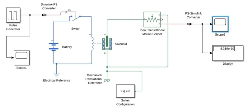
- The pulse generator is used to create square wave pulses at regular intervals.The block waveform parameters Amplitude,pulse width,period and phase delay,determine the shape of the output waveform.
- The switch block used is controlled by external physical signal.If the external signal is greater than the thresold parameter then the switch is closed, otherwise switch is open.
- The positive terminal of the switch is connected to switch and the negative terminal is connected to the electrical reference.
- The Solenoid block is connected with switch and battery and we will get a complete electrical circuit.The port c is connected with mechanical reference.
- The ideal translational sensor is connected with solenoid block R to observe the movement of the plunger.
- Scope is connected with the ideal translational sensor to get the output.
- PS-Simulink converter is used to convert the physical signal to simulink signal.
- Solver Configuration:Each physical network represented by a connected simscape blocks requires solver setting information for simulation
INPUT PULSE GENERATOR PLOT :
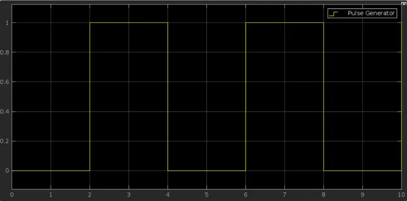
- It’s understood that the time pulse is generated for every 2 seconds to control the switch in a time span of 10 sec.
-
When the switch is closed the solenoid blocks receives electrical power and the plunger move from port R to c to hit the bell and produce sound.
OUTPUT POSITION PLOT :
- From the position plot it’s understood that the bell is rung for every 2 sec in a time span of 10 sec
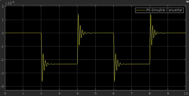
- If the solenoid parameter is set as 'Port R moves toward port C', following negative waveform is obtained.
CONCLUSION :
- In order to obtain the simulation of the doorbell a solenoid is used which convert the electrical energy into mechanical energy
and form a simulation accordingly. - The motion of the plunger was simulated and recorded and plotted by using an ideal motion sensor and scope.
2.Use a Thermistor To Sense The Temperature Of a Heater & Turn On Or Turn Off The Fan As Per The Given Conditions:
THERMISTOR :
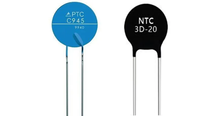
A thermistor is a type of resistor whose resistance is strongly dependent on temperature, more so than in standard resistors. The word is a combination of thermal and resistor. Thermistors are widely used as inrush current limiters, temperature sensors (negative temperature coefficient or NTC type typically), self-resetting overcurrent protectors and self-regulating heating elements (positive temperature coefficient or PTC type typically).
Thermistors are of two opposite fundamental types :
- With NTC thermistors, resistance decreases as temperature rises usually due to an increase in conduction electrons bumped up by thermal agitation from valency band. An NTC is commonly used as a temperature sensor, or in series with a circuit as an inrush current limiter.
- With PTC thermistors, resistance increases as temperature rises usually due to increased thermal lattice agitations particularly those of impurities and imperfections. PTC thermistors are commonly installed in series with a circuit, and used to protect against overcurrent conditions, as resettable fuses.
SIMULINK MODEL:
The signal builder generates the time interval with various temperature as a source of heater.
Conditions of Heat Source,
T = 20 Degree Celcius for (0-10 s)
T = 27 Degree Celcius for (10-30 s)
T = 23 Degree Celcius for (30-50 s)
Condition for FAN,
T = Above 25 Degree Celcius - ON
T = Below 25 Degree Celcius - OFF
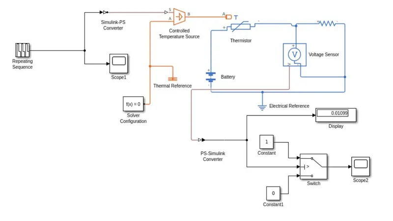
- Controlled Temperature source represents an ideal source of thermal energy,that can maintain a controlled temperature difference regardless of the heat flow rate. The temperature difference is set by the physical signal port S. A positive temperature difference causes the temperature at port B to be greater than the temperature at port A.
- Thermistor is a type resistor whose resistanc eis based upon temperature.
- A linear resistor is used is used inorder to control the amount of current from thebattery.
- The voltage sensor is used to convert the voltage measured between two points into a physical signal.
- The Voltage Source block implements a voltage source with DC, AC, and noise components.
- The Electrical Reference block represents an electrical ground. Electrical conserving ports of all the blocks that are directly connected to ground must be connected to an ElectricalReference block. A model with electrical elements must contain at least one Electrical Reference block.
- Solver Configuration:Each physical network represented by a connected simscape blocks requires solver setting information for simulation.
OUTPUT :
CONCLUSION :
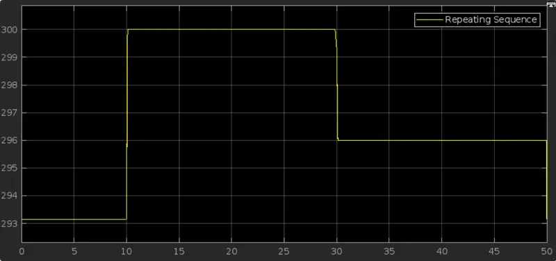
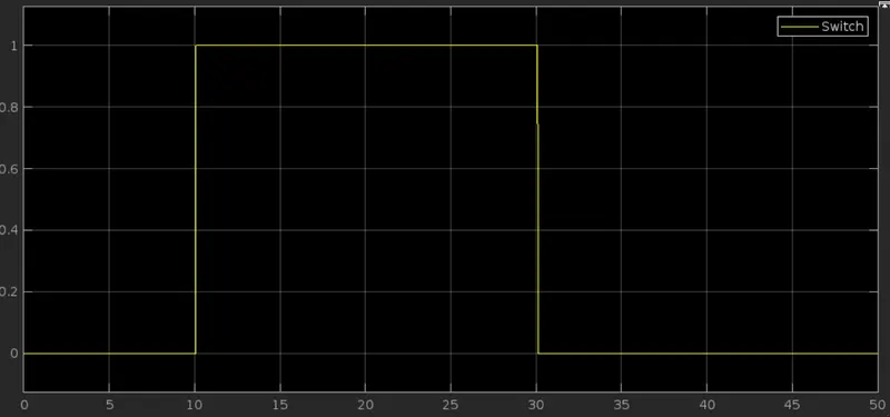
For 0-10 secs fan is in OFF condition, because temperature is 293K which is below 298K. After 10 secs temperature goes to 300K, so fan will turn ON, because temperature exceeds 298K. After 30 secs fan will turn OFF because temperature goes to 296K which is below 298K.
From the above results the given condition has been acheived and succesfully executed.