Week -2
- Make a Simulink model of Doorbell using solenoid block with the following details:
In the above arrangement, when the switch is closed the electromagnet receives electrical power from the battery and pulls the metal arm to hit the bell producing sound.
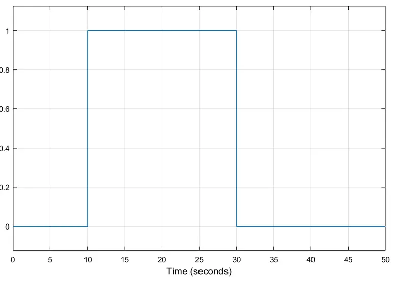
Create a situation where the switch is closed for 2 seconds and then released. Observe the physical movement of the plunger.
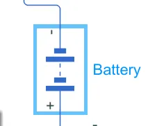
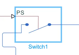
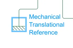
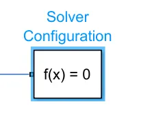
components used:
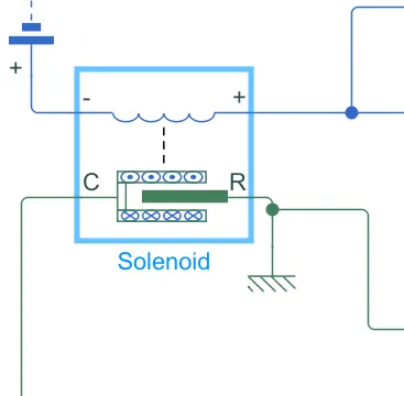
The Solenoid block represents the electrical characteristics and generated force for the solenoid in this figure:
Both positive and negative currents generate a force that pulls the plunger towards the winding. This minimizes the reluctance and decreases the stroke. To increase the stroke, a spring or an external force must overcome the magnetic force.
The return spring is optional. To remove the effects of this spring from the model, set the Spring constant parameter to 0.
To show the direction in which the solenoid acts, the block icon changes dynamically based on value of the Motion direction under excitation parameter.
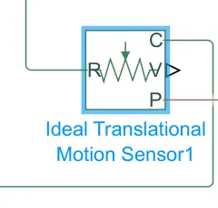
The Ideal Translational Motion Sensor block represents a device that converts an across variable measured between two mechanical translational nodes into a control signal proportional to acceleration, velocity, or position. You can specify the initial position (offset) as a block parameter.
The sensor is ideal since it does not account for inertia, friction, delays, energy consumption, and so on.
Connections R and C are mechanical translational conserving ports that connect the block to the nodes where motion is being monitored. The block positive direction is from port R to port C. This means that the velocity is measured as v = vR – vC, where vR, vC are the absolute velocities at ports R and C, respectively. The Measurement reference parameter lets you disable port C and measure with respect to ground.
Connections A, V, and P are physical signal output ports for acceleration, velocity, and position, respectively. The visibility of these ports is controlled by block parameters. If you enable port A, the block performs additional computations, to measure acceleration based on velocity. To avoid unnecessary model complexity, it is recommended that in each instance of the block you enable only the ports that you actually use for measurement.
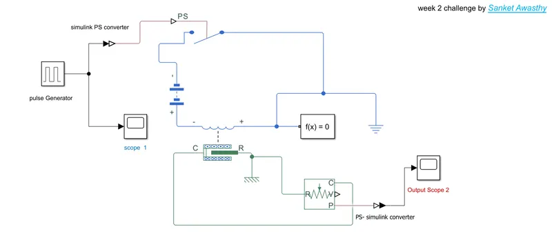
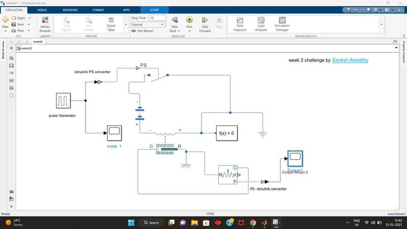
Circuit Diagram ( Connections of blocks in simulink):
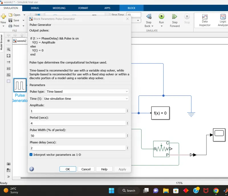
PULSE GENERATOR:
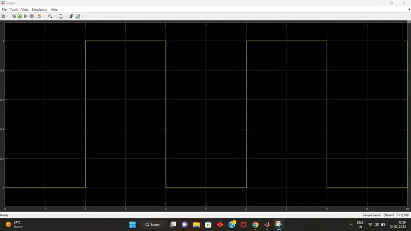
INPUT WAVE FORM OF scope 1:

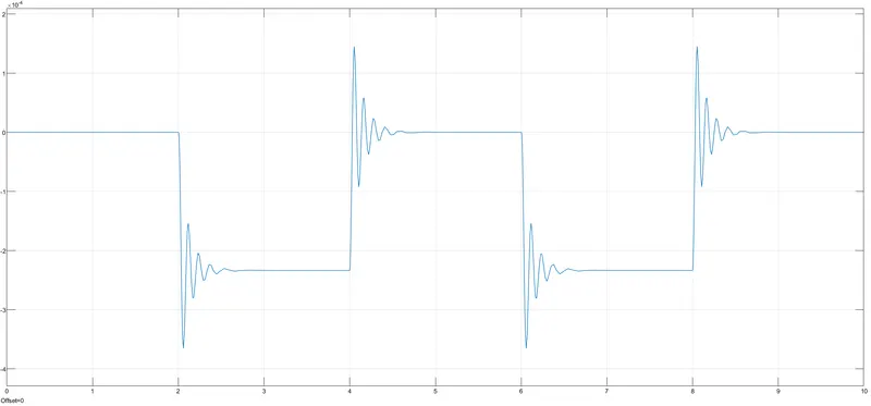
OUTPUT WAVEFORM of Scope 2:

2:
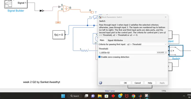
Use a thermistor to sense the temperature of a heater & turn on or turn off the fan as per the below conditions:
Temperature source: 20 °C from 0 to 10 seconds, 27 °C from 10 to 30 seconds, 23 °C from 30 to 50 seconds
Fan conditions: ON if the temperature above 25 °C, OFF otherwise
Thermistors are temperature-dependent resistors, changing resistance with changes in temperature. They are very sensitive and react to very small changes in temperature. They are best used when a specific temperature needs to be maintained, and when monitoring temperatures within 50°C of ambient.

The main use of a thermistor is to measure the temperature of a device. In a temperature controlled system, the thermistor is a small but important piece of a larger system. A temperature controller monitors the temperature of the thermistor. It then tells a heater or cooler when to turn on or off to maintain the temperature of the sensor.
Components used (BLOCKS):

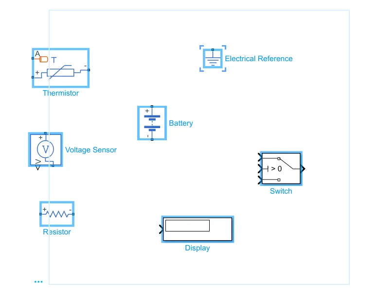
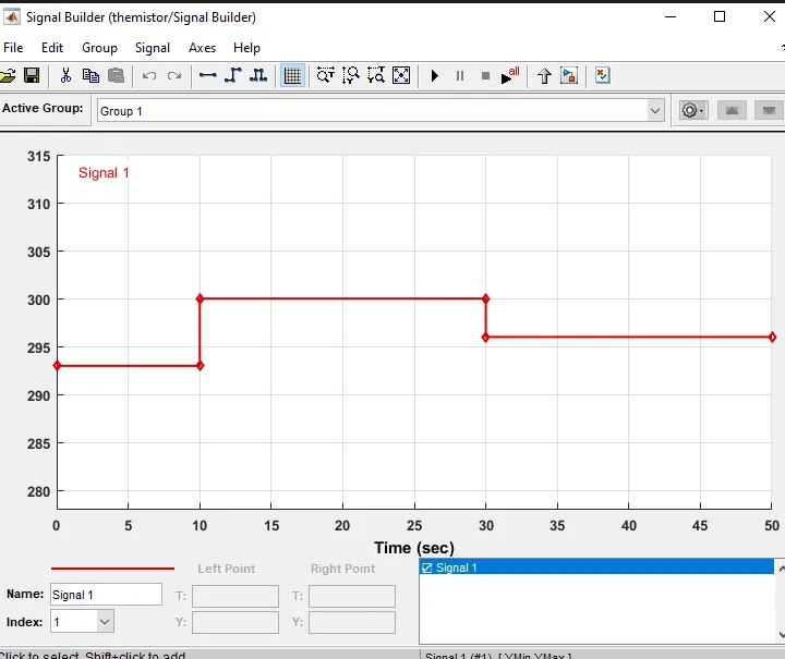
1. 0-10 sec temperature 293
2. 10-30 secs temperature 300
3. 30-50 secs temperature 296
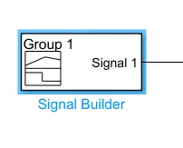
and you can see these details in plot basis in signal builder block where the input is inserted with these signals.
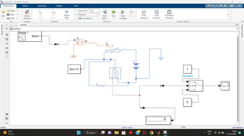
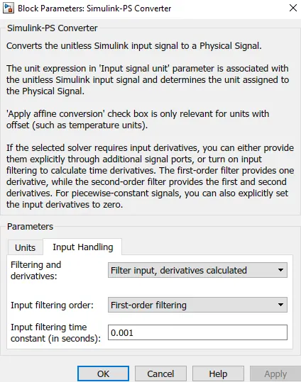
OUTPUT: