Week -2
AIM : To make a simluink model of doorbell using solenoid block &
To sense temperature of heater and turn it on and off using thermistor and other coressponding components.
MODEL OF DOOR BELL :
COMPONENTS AND USAGE :
PULSE GENERATOR : Used to give input pusle signals.
BATTERY : Acts as power source to the system
SWITCH : They act as control unit for entire system. Here switch of two inputs is used,one is connected to battery and another is connected to pusle generator.
SIMULINK-PS : Converts simulink signal to physical signal.
PS-SIMULINK : Converts physical signal into simulink.
ELECTRICAL REFERENCE AND MECHANICAL REFERENCE : Both represent grounding the system and mechanical reference denotes making a reference point which means a fixed frame.
IDEAL TRANSLATIONAL MOTION SENSOR : Measures velocity and displacement.Port V & P represent displacement and velocity respectively.
SOLVER CONFIGURATION : Helps us to solve simulation through solver settings.
SCOPE : Displays output in graphical form.
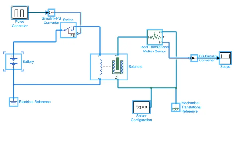
figure 1
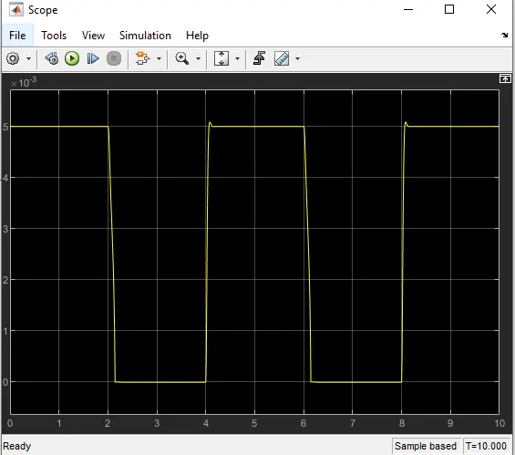
figure 2 ( we could see decrease in displacement gradually when plunger gets close to the bell and increase when moves away. This is represent with respect to position of ports R&C in solenoid. Port R moves towards port C they are considered as plunger and bell respectively.)
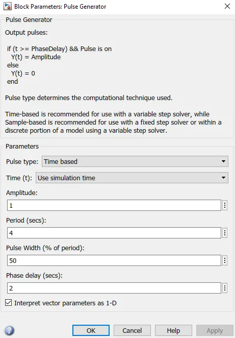
figure 3 (switch can be closed for 2 seconds by adjusting phase delay. Stop time is taken as 10)
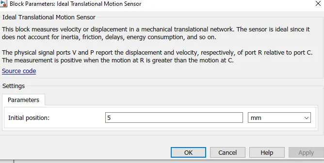
figure 4
THERMISTOR (TO SENSE TEMPERATURE) :
COMPONENTS AND USAGE :
REPEATING SEQUENCE STAIR : It consists of discrete values which we provide.
THERMAL REFERENCE : Acts as thermal reference point where temperature is absolute zero. Here it is connected to port A of temperature source.
CONTROLLED TEMPERATURE SOURCE : Used to maintain a controlled temperature difference. Port S represents temperature difference. Port A & B is used to connect to the system.
THERMISTOR : Used to measure temperature in a circuit with respect to resistor as resistance is dependant on temperature. Port A is connected to port B of temperature sensor.
RESISTOR : Provides resistance to the circuit. It is connected to thermistor and battery.
VOLTAGE SOURCE : Measures volatage signal by converting it into a physical signal.
BATTERY : Acts as power source to the system
SWITCH : They act as control unit for entire system. Two constant block is connected which reprensents position of switch. second input in switch is connected voltage sensor.
SIMULINK-PS : Converts simulink signal to physical signal.
PS-SIMULINK : Converts physical signal into simulink.
SOLVER CONFIGURATION : Helps us to solve simulation through solver settings.
SCOPE : Displays output in graphical form.
Condition for switch to turn on is when temperature is greater than 25.
Here the condition of fan to turn on or off with respect to change in temperature is provided as threshold change. when threshold is greater than 0 then switch is turned on else it remains off
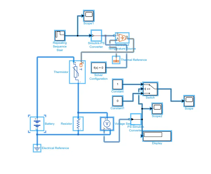
figure 1
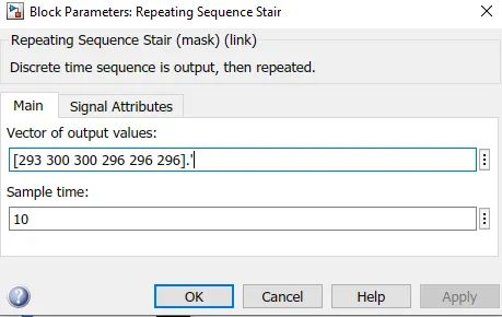
figure 2 (the values of temperature 20,27&23 are represented and given in kelvin. A sample time of 10 seconds is assigned)
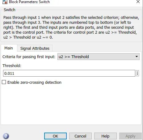
figure 3 (threshold value after simulation)
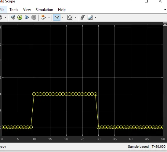
figure 4 ( we could see when time is between 10-30 ,the position of switch is turned on as temperature is above 25 degrees and maximum of threshold is obtained.)