Week -2
AIM
To Make a Simulink model of Doorbell using solenoid block and To use a thermistor to sense the temperature of a heater & turn on or turn off the fan with the given data.
GIVEN PARAMETERS
DOOR BELL
Door bell using solenoid for reference.
In the above arrangement, when the switch is closed the electromagnet receives electrical power from the battery and pulls the metal arm to hit the bell producing sound. Create a situation where the switch is closed for 2 seconds and then released. Observe the physical movement of the plunger. And assume the remaining parameters.
THERMISTOR
Temperature source: 20 °C from 0 to 10 seconds, 27 °C from 10 to 30 seconds, 23 °C from 30 to 50 seconds. Fan conditions: ON if the temperature above 25 °C, OFF otherwise.
DEFINITION
SOLENOID
A solenoid is a device comprised of a coil of wire, the housing and a moveable plunger (armature). When an electrical current is introduced, a magnetic field forms around the coil which draws the plunger in. More simply, a solenoid converts electrical energy into mechanical work.
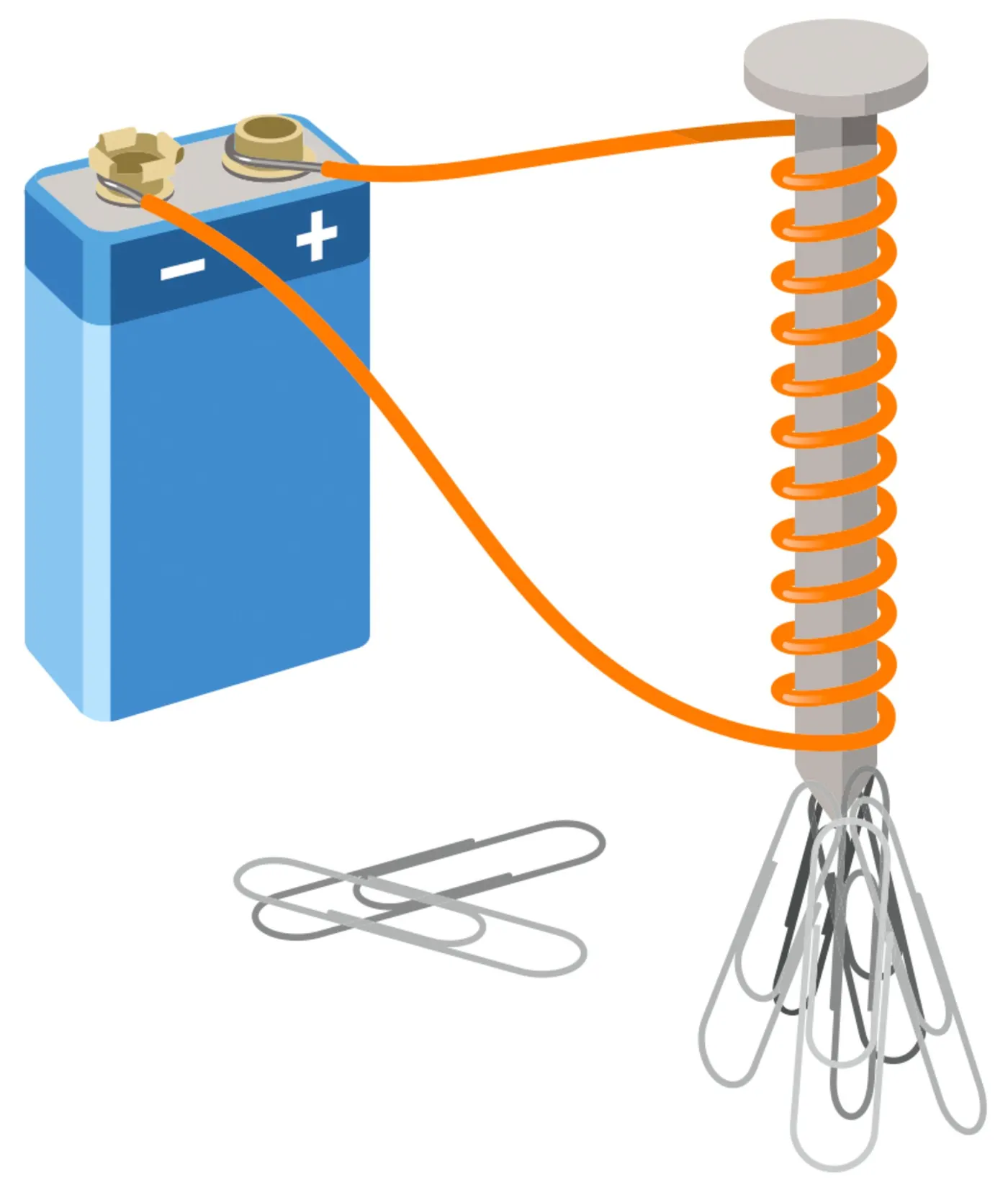
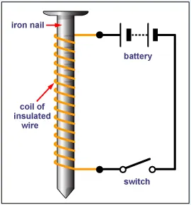
The Nail which is woundeed by the coil is made to pass the current through itby the battery. By passing the current through the windings the nail gets charged and creates a magnetic field arond it.
THERMISTOR
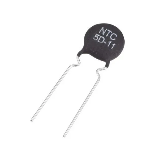
A thermistor is a type of resistor whose resistance is dependent on temperature, more so than in standard resistors. The word is a combination of thermal and resistor. Thermistors are widely used as inrush current limiters, temperature sensors (negative temperature coefficient or NTC type typically), self-resetting overcurrent protectors, and self-regulating heating elements (positive temperature coefficient or PTC type typically).
Thermistors are of two opposite fundamental types:
- With NTC thermistors, resistance decreases as temperature rises. An NTC is commonly used as a temperature sensor, or in series with a circuit as an inrush current limiter.
- With PTC thermistors, resistance increases as temperature rises. PTC thermistors are commonly installed in series with a circuit, and used to protect against overcurrent conditions, as resettable fuses.
SOLUTION
(a) A Simulink model of Doorbell using solenoid block
Blocks used here
- Pulse Generator
- Scope
- Simulink-PS Converter
- Battery
- PS Switch
- Solenoid
- Ideal Translational Motion Sensor
- Solver Configuration
- Ps-Simulink Converter
These blocks are explained in the description of the model below.
Model
Description
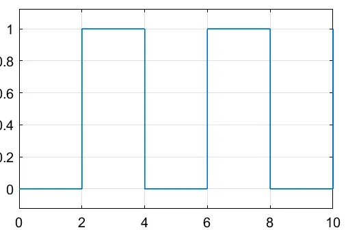
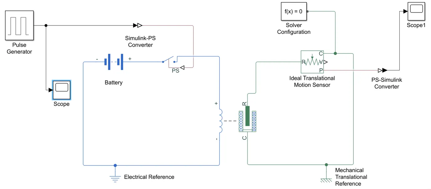
First the Pulse Generator block is used to generate the input signals such as when the switch is closed the electromagnet receives electrical power from the battery and pulls the metal arm to hit the bell producing sound. Create a situation where the switch is closed for 2 seconds and then released. To get a graphical represnetation of the input signals we are connecting a Scope to it. Pulse type determines the computational technique used, Which is to be connected to the Switch block.
SWITCH BLOCK
The block represents a switch controlled by an external physical signal. If the external physical signal PS is greater than the threshold, then the switch is closed, otherwise the switch is open. The closed resistance is defined by parameter R_closed, and the open conductance is defined by parameter G_open. Both parameters must be greater than zero.
Since switch block is a simscape physical system, The input values are converted into the equivalent signal using Simulink-PS Converter, to pass the inputs to the switch.
One of the switch terminal is connected to the positive terminal of the windings of the solenoid and the other terminal of the switch is connected to the positive terminal of the Battery block. And the negative terminal of the battery is connected to the negative terminal of the windings of the solenoid.
Now coming to the Solenoid block the port R moves towards the prot C, thus the port R gives the translational motion, so the translational motion of the port R (plunger) is observed using the Ideal Translational Motion Sensor.
IDEAL TRANSLATIONAL MOTION SENSOR
This block measures velocity or displacement in a mechanical translational network. The sensor is ideal since it does not account for inertia, friction, delays, energy consumption, and so on. The physical signal ports V and P report the displacement and velocity, respectively, of port R relative to port C. The measurement is positive when the motion at R is greater than the motion at C.
Now the port C of the solenoid block and this sensor are connected to each other. And as the port P reports the velocity that is taken into account and connected to the Scope to get the graphical representation of the output signals of the door bell. as the signal from the sensor should be converted into equivalent value in order to get into the scope. so we need a PS-Simulink converter between the Ideal translational Motion Sensor and Scope.
Thus the input signals were given through the Pulse generator. When the graph line is in 0 the switch is open and the current wont be passing on hence the circuit is Off. And when the graph line is in 1, the switch is closed hence the current will be passing through it, hence it indicates On.
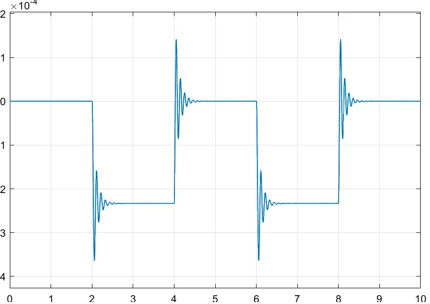
Now this is graph obtained at the first, Here in this graph we can observe that the graph starts at the point 0. And this graph indicates the displacement of the plunger, Hence this graph starts at 0, this is wrong indication there wont be any contact of the plunger and the bell at the initial condition. Hence we have to increase the increase displacement in the sensor block.
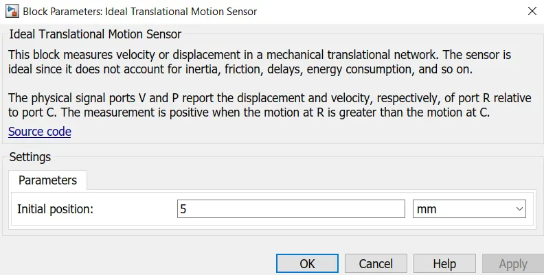
Initially it was 0mm, and now the position is made to 5mm. And this leads to the result below.
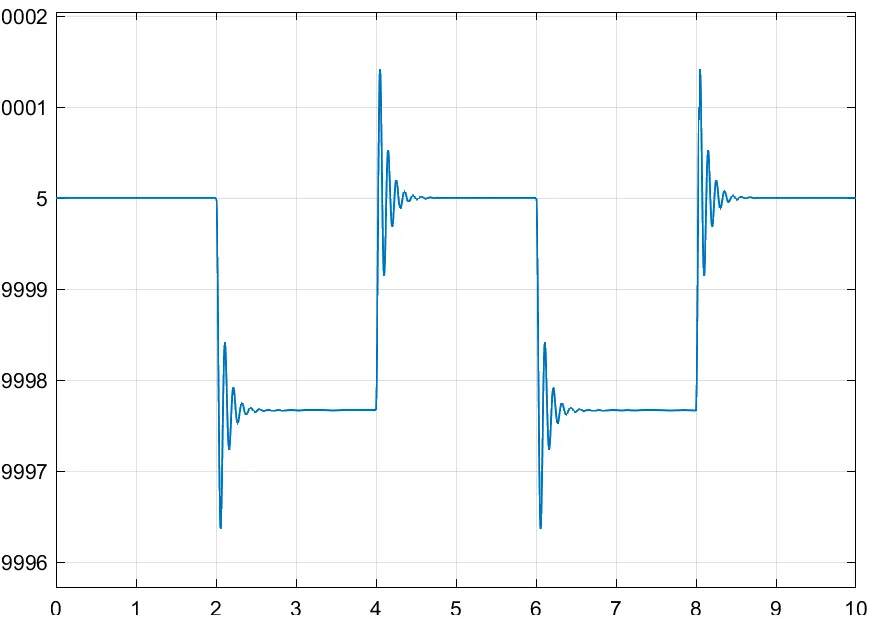
Here the graph starts at 5 but now the plunger is not touching the bell ie., 0. Because when the plunger touches the bell, it vibrates and produces sound. in order to make the pplunger move towards the bell, the parameters of the Solenoid is varied as below.
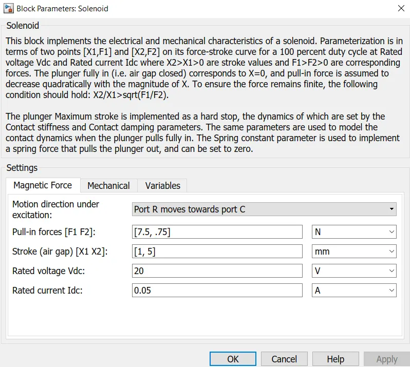
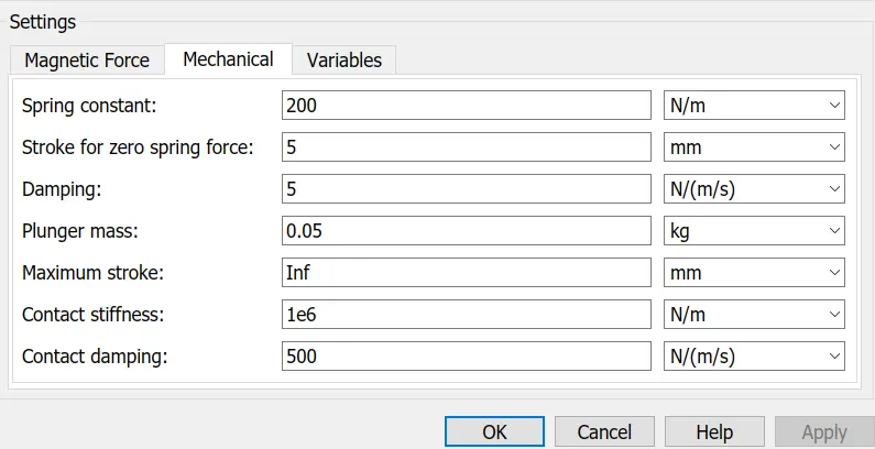
Rated voltage is decreased to 20V and Damping is increased to 5N/(m/s). Now the plunger touches the 0point for given 2seconds.
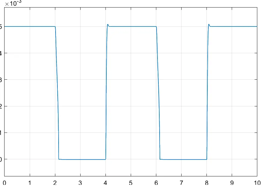
Thus this is the graph representing the output signals we get out of the scope1 connected to the translational sensor.
(b) Using a thermistor to sense the temperature of a heater & turn on or turn off the fan
Blocks used here
- Repeating Sequence Stai
- Scope
- Simulink-PS Converter
- Controlled Temperature source
- Thermal Reference
- Thermistor
- Battery
- Electrical Reference
- Resistor
- Voltage Sensor
- Ps-Simulink Converter
- Switch
- Display
- Constant
Model
Description
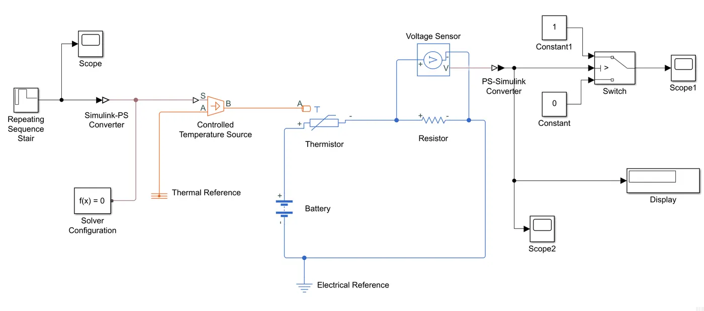
First the input temperature values were given in the Repeating Sequence Stair block, with assigning the given temperature values.
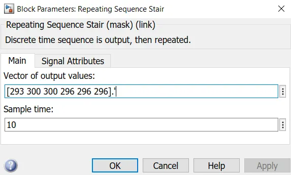
A Scope is connected to the output from the repeating sequence stair block and the graph for the input values is attached below.
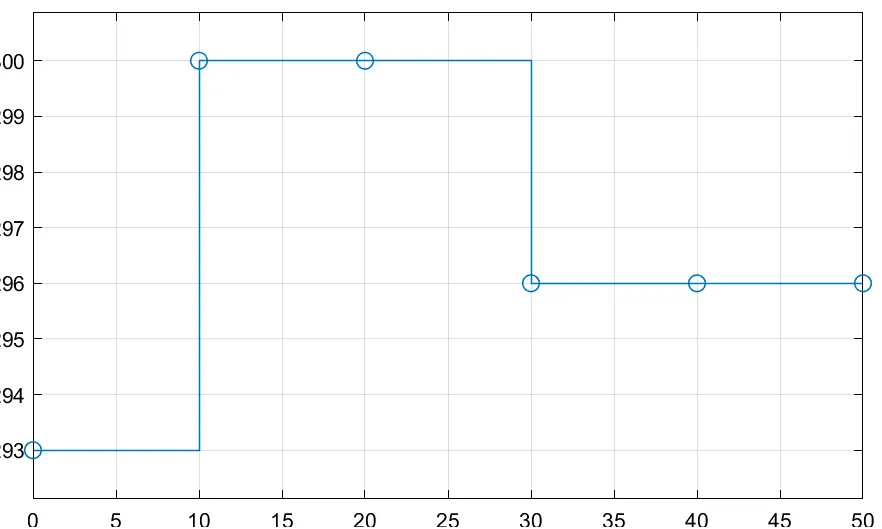
This input temperature values should be given to the Thermistor, But here we are adding a Controlled Temperature Source which gives a certain temperature flows through it even it passes above the given criteria. And here to pass the input value, Simulink-PS Converter is used to convert the input signals passes into the physical systems.
Solver Configuration is used as it is necessary here so it is connected in the circuit between Simulink -PS converter and Controlled Temperature Source.
CONTROLLED TEMPERATURE SENSOR
This block represents an ideal energy source in a thermal network that can maintain a controlled temperature difference regardless of the heat flow rate. The temperature difference is set by the physical signal port S. A positive temperature difference causes the temperature at port B to be greater than the temperature at port A. And Port A is connected to the Thermal Reference.
Here comes the main segment, Thermistor block, Q is the net heat flow into port A.
The output from the Controlled Temperature Source is given as a input in Thermistor. The positive terminal of the thermistor is connected to the positive terminal of the battery. And the negative terminal of the battery is grounded with the help of Electrical Reference. And also the negative terminal of the battery is connected to the negative terminal Resistor and the positive terminal of the resistor is connected to the Thermistor.
The voltage in the resistor should be sensed by using Voltage Sensor by connecting it with the positive terminals of the resistor and Voltage sensor and negative terminals of the resistor and Voltage sensor together.
VOLTAGE SENSOR
The block represents an ideal voltage sensor, that is, a device that converts voltage measured between any electrical connections into a physical signal proportional to the voltage. Connections + and - are conserving electrical ports through which the sensor is connected to the circuit. Connection V is a physical signal port that outputs voltage value.
From the V, there comes the output which to be connected to the Switch block, to turn the fan on and off. But before connecting it with the switch, the it should be converted using PS-Simulink Converter and then it should be directed to the Switch block.
SWITCH
Pass through input 1 when input 2 satisfies the selected criterion; otherwise, pass through input 3. The inputs are numbered top to bottom (or left to right). The first and third input ports are data ports, and the second input port is the control port. The criteria for control port 2 are u2 >= Threshold, u2 > Threshold or u2 ~= 0.
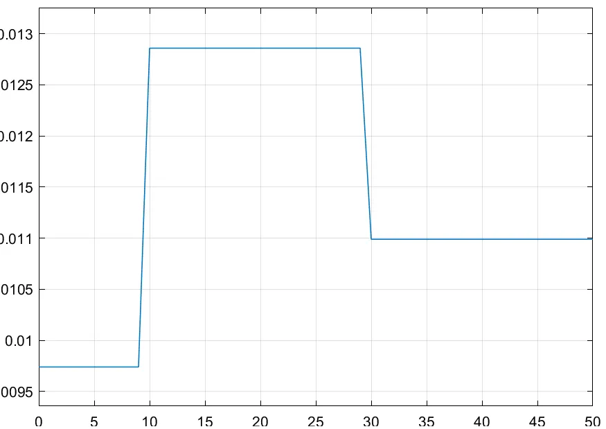
Threshold voltage should be given in the switch block to assign a condition that whether the switch condition should be in on or off condition. Here our Threshold velocity is 0.01099 and for the cases above or equal to this velocity the switch must be in on condition and for the below condition the switch must be in off condition. And here the input 1 and input 2 is given as 1 and 0 respectively.
Thereby a Scope is connected with the input1 of the switch to get the condition of the fan in a graphical representation. And a Scope is attached to the line of the value befor connecting it with the switch inorder to find the threshold velocity and a Display is connected to display the threshold velocity value.
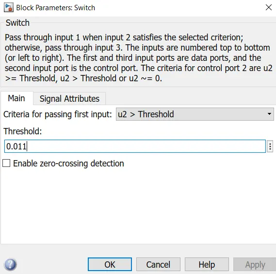
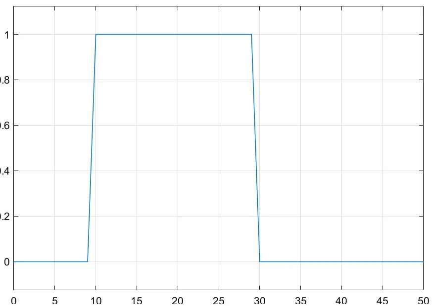
And thus hereby,from the graph above concluding that the fan's condition will be OFF for 0 - 10 seconds, and ON for 10 - 30 seconds and will be in OFF condition for 30 - 50 seconds.
LEARNING OUTCOMES
The Usage of PS-Simulink and Simulinnk -PS converter were learnt and the parameters of those Solenoid and sensor blocks were lerant and how they are related to the result outcomes were learnt. Switch block parameters were newly learnt in this.
CONCLUSION
Thus a Simulink model of Doorbell using solenoid block with given criteria, a model is built in Simulink and Using a thermistor to sense the temperature of a heater & turn on for the temperature above 25C and turn off the fan for the temperature below 25C model is also done.