Week -2
AIM
- Make a Simulink model of Doorbell using solenoid block with the following details:
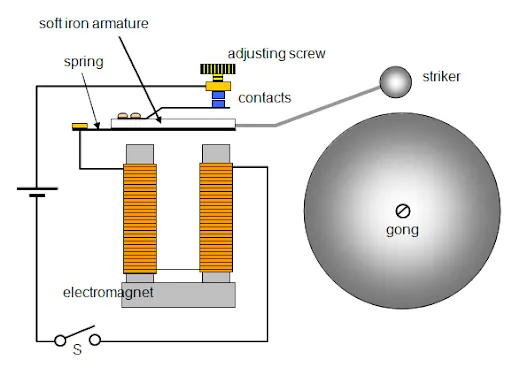
In the above arrangement, when the switch is closed the electromagnet receives electrical power from the battery and pulls the metal arm to hit the bell producing sound.
Create a situation where the switch is closed for 2 seconds and then released. Observe the physical movement of the plunger.
Assume remaining parameters.
- Use a thermistor to sense the temperature of a heater & turn on or turn off the fan as per below conditions:
Temperature source: 20 °C from 0 to 10 seconds, 27 °C from 10 to 30 seconds, 23 °C from 30 to 50 seconds
Fan conditions: ON if the temperature above 25 °C, OFF otherwise
DIAGRAM
THEORY
SOLENOID
A solenoid is a device comprised of a coil of wire, the housing and a moveable plunger (armature). When an electrical current is introduced, a magnetic field forms around the coil which draws the plunger in. More simply, a solenoid converts electrical energy into mechanical work.
- The coil is made of many turns of tightly wound copper wire. When an electrical current flows through this wire, a strong magnetic field/flux is created.
- The housing, usually made of iron or steel, surrounds the coil concentrating the magnetic field generated by the coil.
- The plunger is attracted to the stop through the concentration of the magnetic field providing the mechanical force to do work.
The given diagram below is a representation of the electric bell using a solenoid.
When the circuit is completed the solenoid will get activated and will attract the striker striking the gong and then afterwards the circuit will break.
SIMULINK MODEL
RESULTS
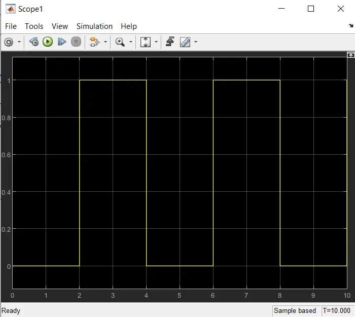
This is the image of the scope connected to the pulse generator
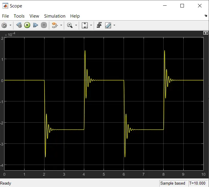
This is the image of the scope connected to the 'Ideal Translational Motion Sensor'
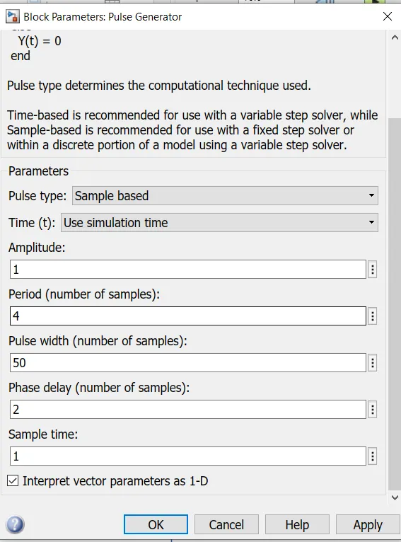
This is the image inside the Pulse generator block
EXPLAINATION
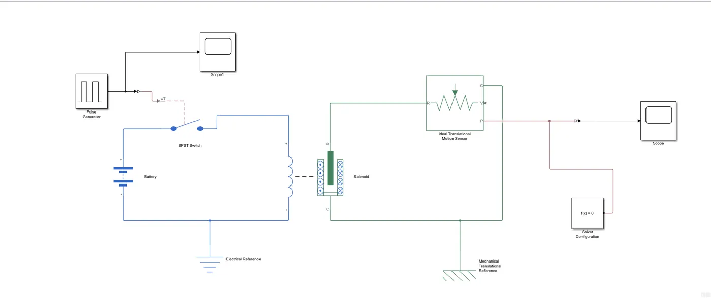
The left side of the circuit is for the coils that are wounded on the solenoid.
The coil is connected to the switch, battery and an electrical reference i.e an earthing.
The switch is connected to the pulse generator that provide the desired pulse to turn on and off the switch.
There is a scope block connected to the output of the pulse generator to observe the type of pulse and its time.
Here the Pulse produced is of the amplitude ‘1’ and with a period of 4 sec with a width of 50% meaning the pulse will be of amplitude 1 for 2 sec and 0 the other 2 sec.
The right side of the circuit is for the observation of movement of the plunger that is inside the solenoid. The solenoid ‘R’ port is connected to the ‘R’ port of the ‘Ideal Translational motion sensor’.
The Ideal Translational motion sensor detects the translation motion of the plunger and gives the output in terms of its ‘velocity’ and ‘position’ through the ‘V’ and ‘P’ port respectively.
Since we are interested in the position only, so we have connected the ‘P’ port to the scope for observation.
Here we can observe the position which starts from ‘0’ and then goes between ‘-2’ and ‘-3’ when the pulse is given. After 2 sec the plunger returns back to the position it started from.
The waves that we are observing in the scope block is the discipation of the shock created while the plunger movement. We can change the graph by assigning values of spring constant and damping coefficient in the solenoid block.
The right side of the circuit is connected to a mechanical reference block. And a solver is connected to the circuit to solve the given set of equations.
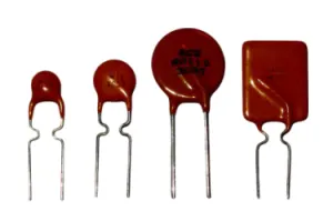
DIAGRAM OF THERMISTORS
THEORY
A thermistor is a resistance thermometer, or a resistor whose resistance is dependent on temperature. The term is a combination of “thermal” and “resistor”. It is made of metallic oxides, pressed into a bead, disk, or cylindrical shape and then encapsulated with an impermeable material such as epoxy or glass.
There are two types of thermistors: Negative Temperature Coefficient (NTC) and Positive Temperature Coefficient (PTC). With an NTC thermistor, when the temperature increases, resistance decreases. Conversely, when temperature decreases, resistance increases. This type of thermistor is used the most.
A PTC thermistor works a little differently. When temperature increases, the resistance increases, and when temperature decreases, resistance decreases. This type of thermistor is generally used as a fuse.
Typically, a thermistor achieves high precision within a limited temperature range of about 50ºC around the target temperature. This range is dependent on the base resistance.
SIMULINK MODEL
RESULTS
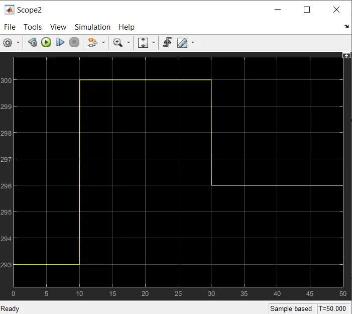
This is the image of the scope connected to the Signal Builder block
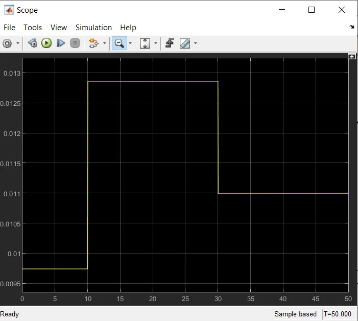
This is the image of the scope connected to the output of the voltage block
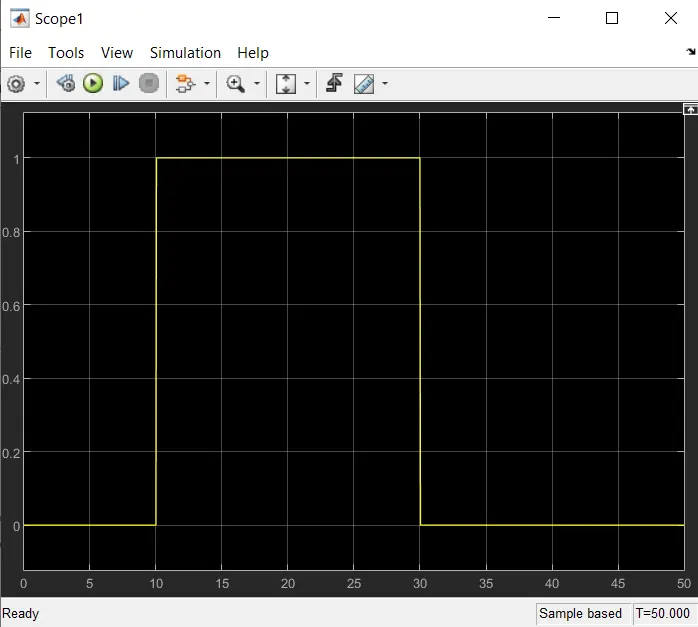
This is the image of the scope connected to the output of the switch block
EXPLAINATION
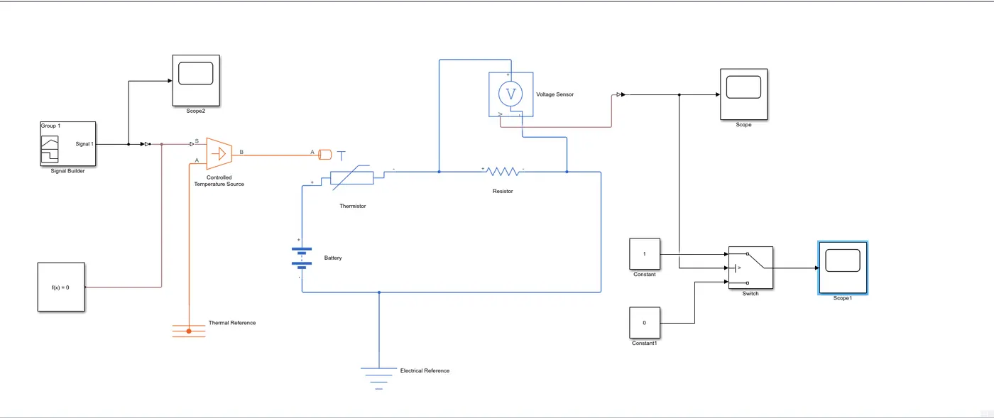
Here we are making an arrangement that will sense the temperature and will turn on and off the fan for the desired temperature condition.
For this project we have to turn on the fan when the temperature goes above 25 degree Celsius.
In the given project the temperature and time are related as following
From 0-10 sec the temperature will be 20 degrees.
From 10-30 sec the temperature will be 27 degrees.
From 30-50 sec the temperature will be 23 degree.
According to this the fan should be switched on from 10-30 sec and switch of for the rest of the time.
We will use a ‘controlled temperature source’ block which gives the desired output no matter the amount of Heat generated. For providing the input to the ‘Controlled Temperature Source’ we will use a signal builder block which will generate the above given conditions. We can see this int the graph provided above.
ABOUT THERMISTORS:- There are 2 types of thermistors mainly the one which increases the resistance with increase in temperatures and the one which decreases the resistance with increase in temperature
The thermistor will detect the temperature and its resistance will increase or decrease with respect to temperature. For different types of Temperatures the thermistor will give different readings, Which we will measure by attaching the voltmeter block across the resistance and will take a look in the scope block.
Under the scope block attached to the voltmeter we observe that when the temperature is 20 degrees the line is in between 0.01-0.0095.
When the temperature is 27 degrees the line is in between 0.0125-0.013 and when the temperature is 23 degrees the line is in between 0.01098-0.011.
As I have found out that when the temperature is 25 degrees the line is almost equal to 0.0118938.
The output of the voltmeter is connected to the switch.
The switch has three input and one output, among that the first and the third input are the conditions which we will give and the second input will be connected to the output of the voltmeter.
We will assign the ‘Threshold’ value in the switch as ‘0.0118938’ as this number will be displayed for 25 degrees.
If the value of the output of the voltmeter goes beyond the ‘Threshold’ value the signal will be given as ‘1’ which will in turn give the signal to switch on the fan and if the output value is less than the ‘Threshold’ value then the signal will be given as ‘0’ and a signal will be send to switch off the fan.
We can observe the scope block attached to the switch block. The value is ‘1’ between 10-30 sec as the temperature is beyond 25 degrees and for the rest of the time the value is ‘0’.
CONCLUSION
Hence the above two experiment are done successfully.