Week -2
Ans1:-
Simulink Model:-
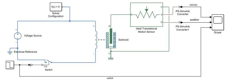
Used Blocks:-
1. Voltage Source (DC, 50V)
2. Electrical Reference
3. Step (Step time - 2sec, Initial value - 1, final value - 0)
4. Switch
5. PS-Simulink converter
6. Simulink-PS converter
7. Solenoid
8. Mechanical Translational Reference
9. Ideal Translational Motion Sensor
10. Scope
Working Principle:-
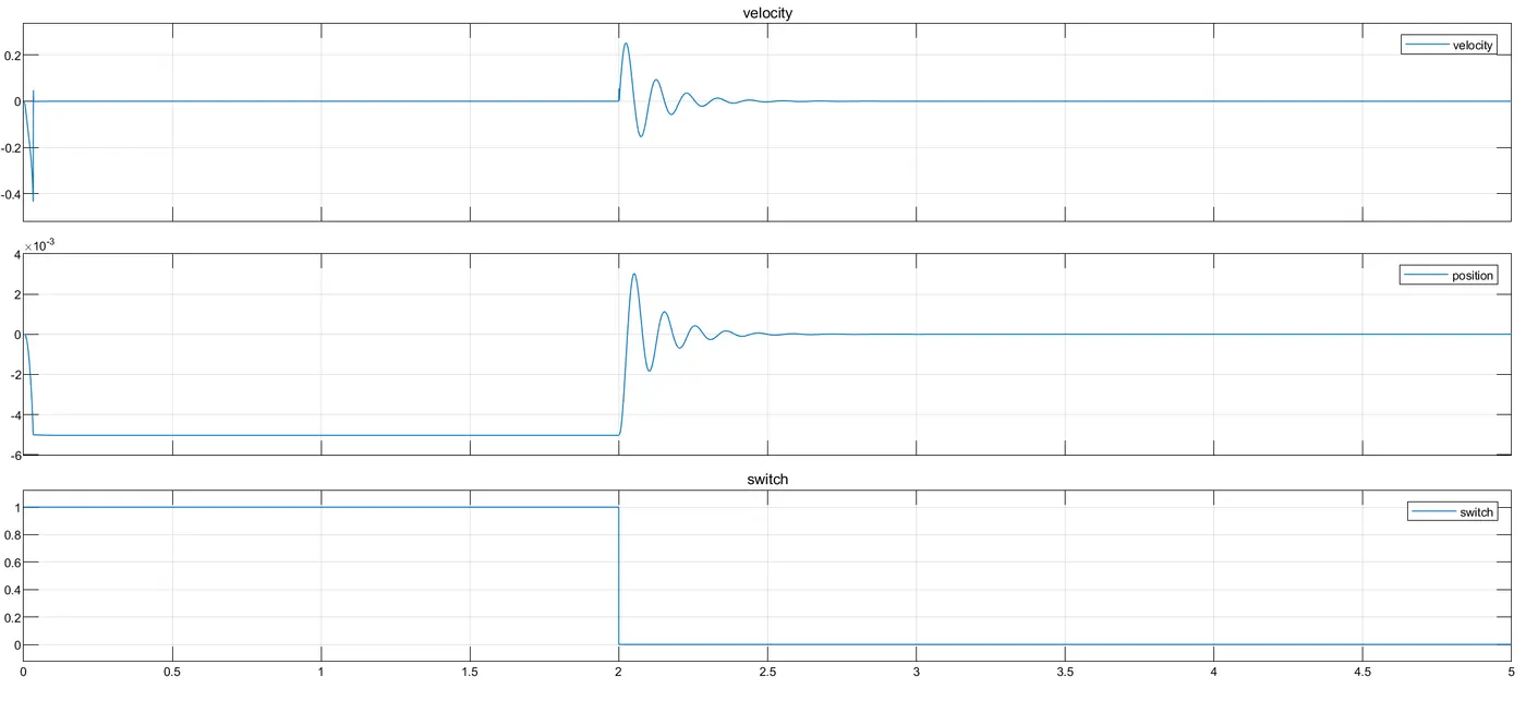
1. t=0 to t=dt (dt<<2) (Transient state)
A positive pulse of 1 amplitude is applied to the switch. The switch turns ON. A DC voltage of 50V builds up between the solenoid coil terminals, causing a positive current to flow from +ve terminal to -ve terminal generating negative magnetic field force (pulling force). The force attracts the plunger (R) towards the case (C) causing a negative displacement and velocity. The velocity abruptly comes to zero at t=dt as the magnetic force becomes constant due to the DC voltage source and the plunger comes to a halt. Before going to zero, the velocity becomes +ve for an infinitesimally small time due to the inertia of the plunger.
2. t=dt to t=2 (Steady state)
As the voltage source is DC a constant magnetic force by the solenoid around the plunger maintains the position of the plunger for 2sec.
3. t=2 to t=2+dt (Transient state)
The switch opens due to the step from high to low. The plunger oscillates to and fro due to the spring action before coming to a halt due to damping.
4. t>2+dt (Steady state)
The plunger is at its initial position with zero velocity.
Waveform:-
Ans2:-
Simulink Model:-
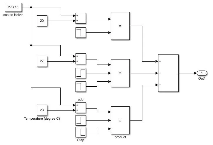
Temperature generator sub-system:-
Used Blocks:-
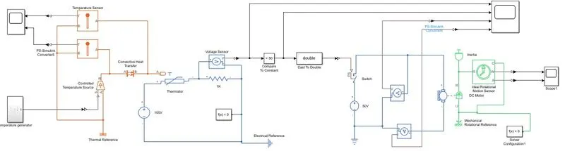
Electrical Blocks -
1. Voltage Source (DC 100V for the Thermistor circuit, DC 50V for the DC motor circuit)
2. Electrical Reference
3. Fixed Resistor (1K)
4. Voltage Sensor (across the fixed resistor, DC motor)
5. Thermistor (T0 - 298.15K (25C), R0 - 1K, B - 3500K, tc - 5sec, Kd - 7.5e-4)
6. Switch
7. DC motor (in place of Fan)
8. Current Sensor
Mechanical blocks -
1. Mechanical Rotational Reference
2. Ideal Rotational Motion Sensor (Input - Plunger movement, Output - angular displacement and angular velocity)
3. Inertia (represents FAN, inertia = 0.01kg/m^2)
Thermal blocks -
1. Controlled Temperature Source (Input - temperature generator sub-system, Output - temperature at port B)
2. Convective heat transfer (Area - 1e-4, heat transfer coefficient - 5e-4)
3. Temperature sensor (at the output of controlled temperature source, at the input of thermister port A)
Simulink blocks -
1. Compare to constant (Input - voltage across fixed resistor, condition - voltage >= 50, output - boolean)
2. Cast to Double (input - boolean, output - double)
3. PS-Simulink converter
4. Simulink-PS converter
5. Scope (Temperature output, voltages and current outputs, switch input, DC motor rotational parameter output (w, a))
6. Solver configuration (for mechanical and electrical systems)
Working Principle:-
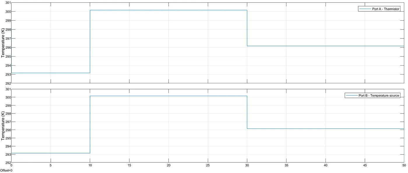
1. The controlled temperature source block generates temperature on port B according to the temperature set on port S.
2. The temperature is set using the temperature generator sub-system.
3. There is a convective heat transfer block that transfers heat from the source to port A of the thermister. (eqn. Q = K.A.(Ta - Tb))
K - Heat Transfer coefficient (W/Km^2) = 5e+4
A - Convective surface area (m^2) = 1e-4
Ta - Tb - Temperature difference between port A and port B
4. - The resistance of the thermistor decreases with an increase in temperature and increases with a decrease in temperature as per thermistor eqn. R = R0.e^(B.(1/T - 1/T0))
R - Thermister resistance
R0 - Reference resistance (1K)
B - Characteristic temperature constant B = 3500K
T - Thermister temperature
T0 - Reference temperature (298.15K)
5. The change in resistance changes the voltage across the fixed resistor block which is sensed by the voltage sensor block.
voltage divider formulae -
V = 100V * 1K / (1K + R)
R - Thermister resistance
V - voltage across fixed-resistance
6. The reference temperature above which we need to turn ON the DC motor is 25C (T0 = 298.15K) at which thermister resistance is R0.
7. By the voltage divider formulae we get the reference voltage across the fixed resistor.
Vref = 100 * 1K / (1K + 1K)
Vref = 50V
8. When the temperature is more than the reference value T0, the resistance falls below R0 taking the voltage across the fixed resistor above the reference value.
9. There is a compare to constant block used which is set for boolean true when voltage > 50V and boolean false when voltage <= 50V
10. The boolean value is cast to double to be able to feed to the switch to control it.
11. The switch turns ON whenever voltage > 50V (thermister temperature T > 298.15K) causes the motor to start.
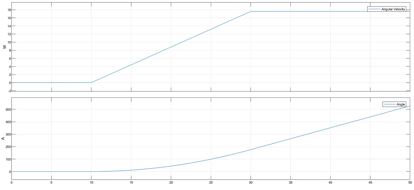
12. The angular velocity is linear between 10 to 30sec as there is a constant current driving the motor. After 30sec the temperature drops below 25C turning OFF the motor and fixing the angular velocity due to the inertia of the fan and the back-emf of the dc motor.
13. The angular displacement still continues to increase linearly as the velocity is constant till 50sec.
Waveforms:-
Temperature -
Electrical characteristics, switch input -
Motor rotational behavior -