Project
Aim:-
1. Understand the working principle of a CVT through an ATV model.
2. Study the open loop ATV model.
2.1. Study the effect of simple gear ratio on the engine RPM for Throttle and Brake input for the given engine data.
2.2. Study the effect of CVT Ratio on CVT secondary RPM.
3. Study the closed loop ATV model.
3.1. Use the CVT Ratio vs velocity lookup table data as the feedback to the CVT and study the effect on output parameters for Throttle and brake input for the given engine data.
Working Principle of CVT (Continuously Variable Transmission):-
1. It consists of the following components:-
1.1. Primary pulley
1.2. Secondary pulley
1.3. Primary variator
1.4. Secondary variator
1.5. Belt
2. When the primary variator moves inward, the secondary variator moves outward. Hence, increasing the radius of the primary variator and reducing that of the secondary variator. Hence, this leads to overdrive.
3. When the primary variator moves outward, the secondary variator moves inward. Hence, increasing the radius of the secondary variator and reducing that of the primary variator. Hence, this leads to speed reduction.
4. CVT provides a variable gear ratio to transfer power dynamically.
5. It has its applications in ATV and other places where we don't want to change the input power much. It also keeps the engine healthy.
6. Below is the model simulation to verify CVT:-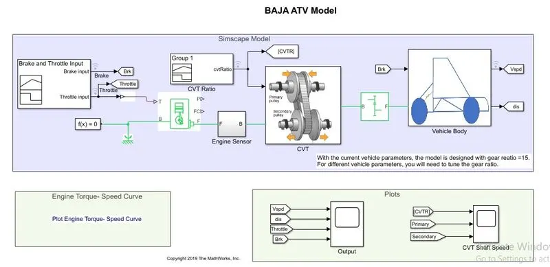
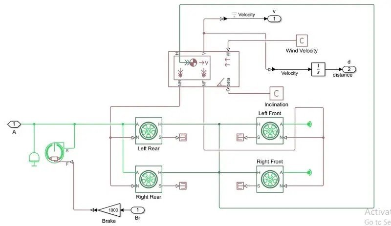
In the above model, the generic engine block generates the power that is then variably transmitted to the output shaft of the vehicle using the CVT block. There is a vehicle body block and Tire block connected that represents a real ATV. Default parameters are used for vehicle body and tire design. The vehicle velocity depends on the CVT secondary RPM and vehicle body parameters like mass, drag, etc, and tire parameters.
Generic Engine block Input/Output characteristics:-
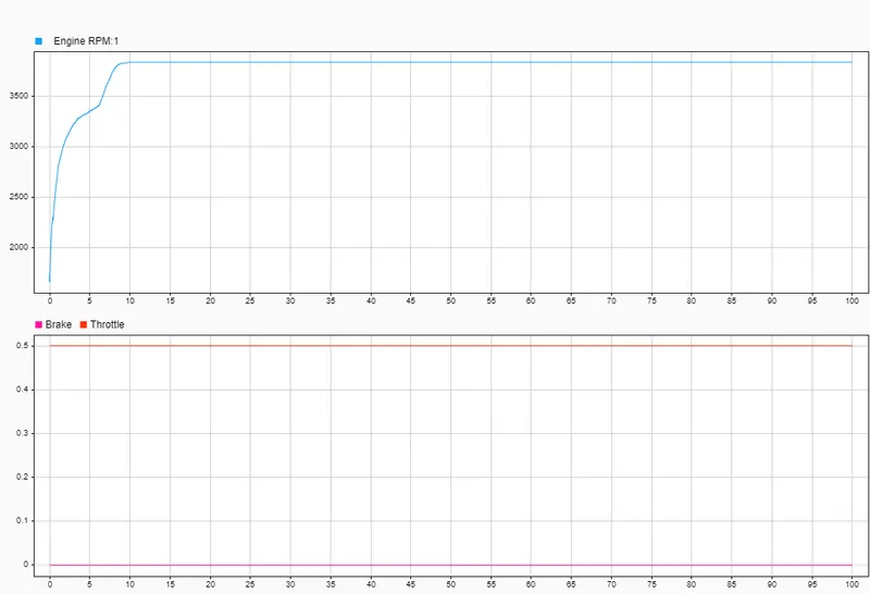
For the given throttle the Engine RPM depends on the TorqueVsSpeed curve data given below -
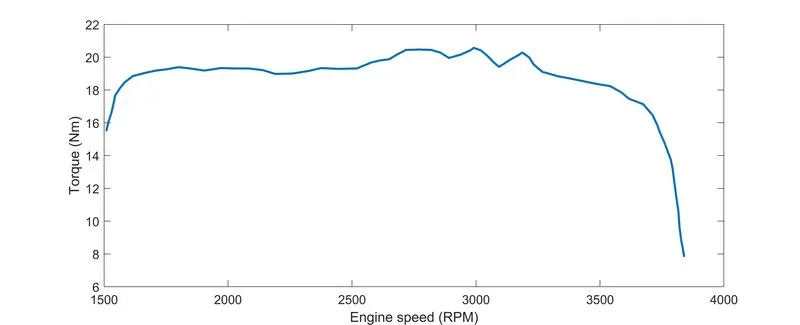
Whether the engine can attain the maximum RPM or not, depends on the amount of throttle fed to it and the simple gear ratio. In our case, the maximum RPM is 3840.
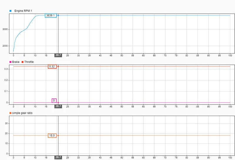
Higher the simple gear ratio lesser amount of throttle required to reach maximum engine RPM. The above results verify the conclusion.
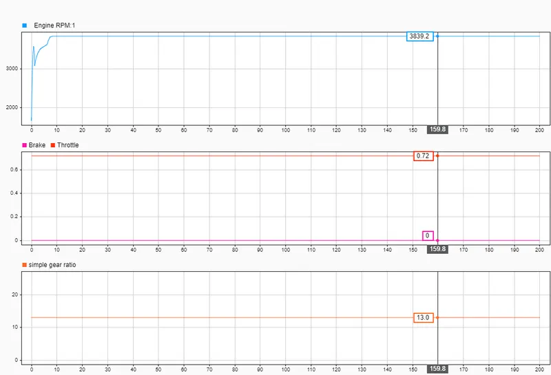
Lower the simple gear ratio more amount of throttle required to reach maximum engine RPM. The above results verify the conclusion.
Cannot increase the throttle above an upper limit for a given simple gear ratio as the engine cannot go beyond the maximum engine RPM. Like in the above-given examples the throttle cannot go beyond 0.72 and 0.32.
A maximum throttle of 1 can be provided to the engine. So if the engine hasn't reached maximum RPM till then, then it can never attain maximum RPM.
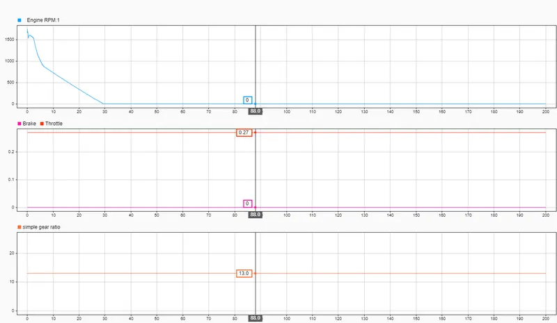
Cannot reduce the throttle below a threshold. It will reduce the engine RPM to zero. Can be justified by the above results.
This means there is an upper and a lower limit to the throttle we can give to the engine for a given simple gear ratio. For ex. for a simple gear ratio of 13. The throttle range from 0.28 to 0.72.
Effect of Brake input on the engine RPM -
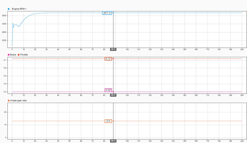
By the above results, it is justified that the more brake we provide lesser will be the steady-state engine RPM and more throttle will be required to reach maximum RPM.
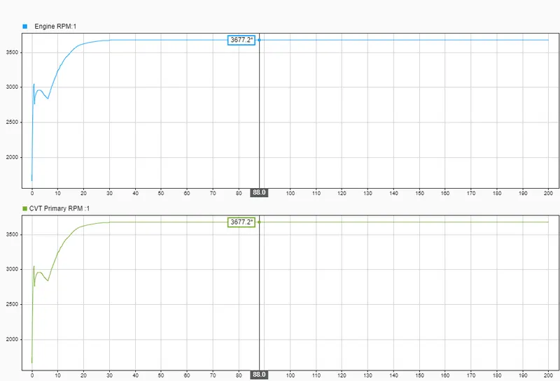
From the simscape model above it can be concluded that the engine RPM and the CVT primary RPM are the same.
CVT Block
Simscape model -
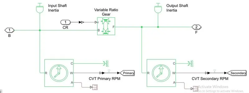
Input to the CVT block - Engine RPM
parameter - CVT Ratio
Output - CVT Secondary RPM
Model input/output characteristics:-
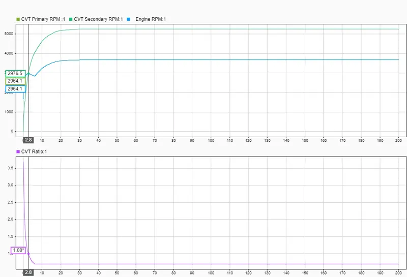
The above result shows that the CVT secondary RPM depends on the CVT ratio input.
When the CVT ratio is greater than 1, the secondary RPM is less than the engine RPM means less power is transmitted as compared to the engine-generated power.
When the CVT ratio is less than 1, the secondary RPM is greater than the engine RPM means more power is transmitted as compared to the engine-generated power.
The variable-ratio gear block is responsible for transferring variable power depending on the CVT ratio for fixed throttle input to the engine. It represents the CVT mechanism.
The Input shaft inertia block and the output shaft inertia block represent the primary and secondary pulley.
Vehicle Body design:-
Model:-
Vehicle velocity vs vehicle mass:-
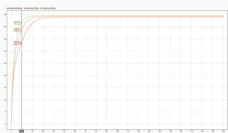
From the vehicle velocity vs vehicle mass graph, one can conclude that a lighter vehicle attains a higher steady-state velocity quicker than a heavier vehicle.
As the vehicle velocity depends on CVT secondary RPM which depends on Engine RPM. These parameters do change as the vehicle velocity changes as the vehicle mass changes.
Closed Loop ATV model:-
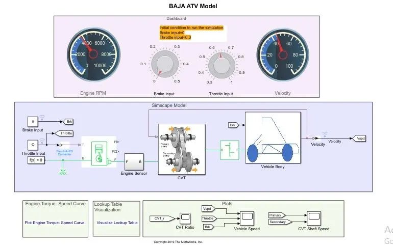
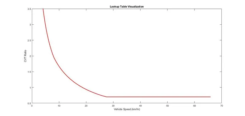
In the closed-loop model, the only difference is the velocity feedback to the CVT Block. There is a lookup table used to convert velocity to CVT Ratio to feed to the Variable Ratio Gear in the CVT Block.
In the open-loop mode, the CVT Ratio was some random data from the signal builder block.
The closed loop system is more realistic as in a real scenario the CVT Ratio depends on the velocity of the vehicle which was ignored in the open loop system.
Closed loop results:-
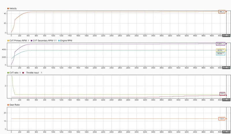
The above results show the effect of the velocity-CVT Ratio lookup table feedback to the CVT Block on the system. The engine attains a maximum RPM of 3840 at less throttle of around 0.6 which was 0.72 in the case of an open loop system for the same simple gear ratio of 13.