Week -2
Solution 1 : Electric Bell Modeling
AIM:
Solution 1 : Electric Bell Modeling
AIM:
To make a Simulink model of Doorbell using Solenoid block.
Description :
In This Switch is closed the electromagnet receive electrical power from the battery and pulls the metal arm hit the bell producing sound.
Simulink model:
Components of Simulink Model:
- Pulse generator
- Scope
- Battery
- Switch
- Electrical reference
- Ideal translation motion sensor
- Solver Configuration
- Mechanical Translation Rerference
- Solver Configuration
- Mechanical translation Reference
Simulink Explanation:
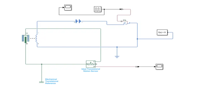
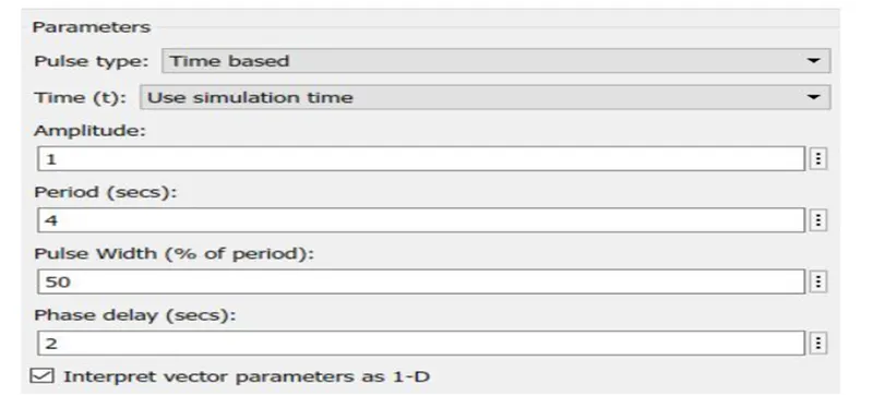
- .The pulse generator is used to create square wave pulses at regular intervals. The block waveform parameters Amplitude, pulse, width, period and phase delay, determine the shape of the output waveform.
- .The switch block used is controlled by external physical signal. If the external signal is greater than the threshold parameter then the switch is closed, otherwise switch is open.
- .The Solenoid block is connected with switch and battery and we will get a complete electrical circuit. The port c connected with mechanical reference.
- .The Ideal translational sensor is connected with solenoid block R to observe the moment of the plunger.
- .Scope is connected with ideal translation sensor to get output.
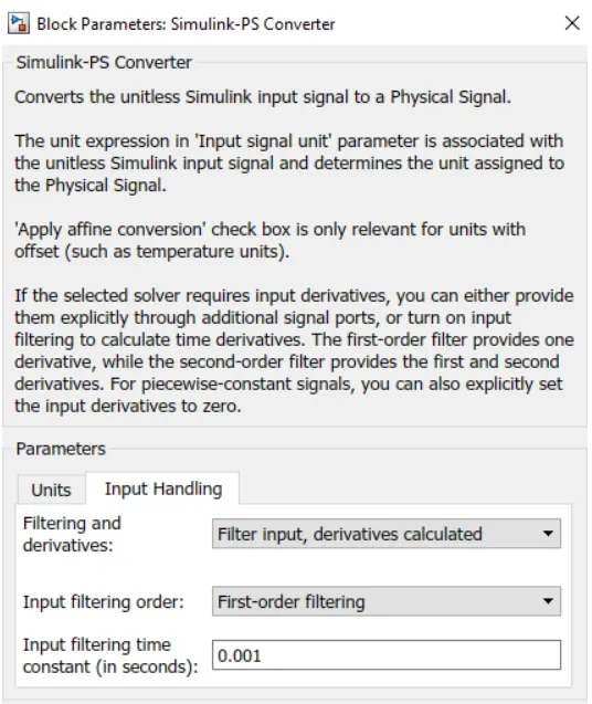
- .Ps-Simulink converter is used to convert the physical signal to simulink signal.
- .Solver Configuration: Each physical network represented by a connected simscape blocks requires solver setting information for simlation
-
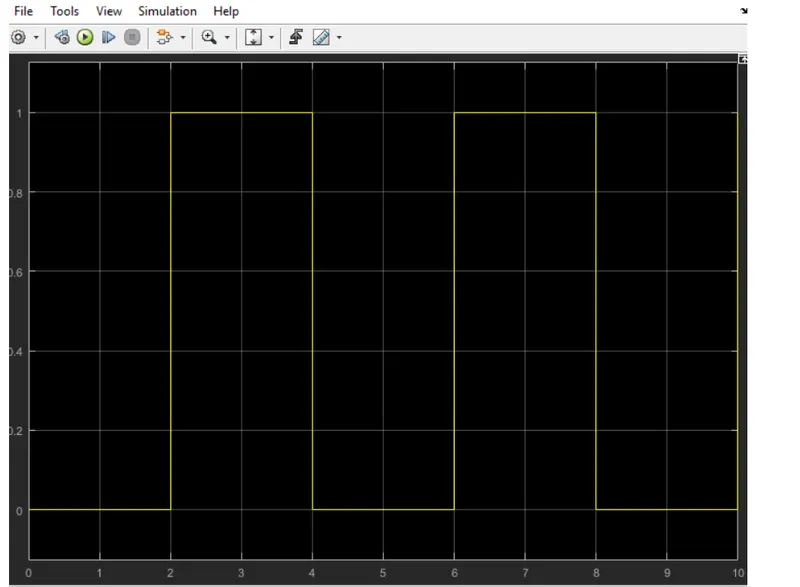
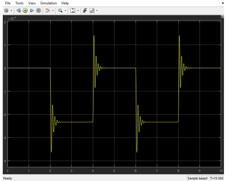
Door bell simulink- wave forms:
Solution-2: Thermistor
- Thermistors are a type of semiconductor, meaning they have greater resistance than conducting materials, but lower resistance than insulating materials.
- Thermistors act as a passive component in a circuit. They are an accurate, cheap, and robust way to measure temperature.
- A thermistor is a device that can be used to establish temperature measurements by correlating the measured value of its electrical resistance to the temperature of the environment or the specific part to which the thermistor has been mounted
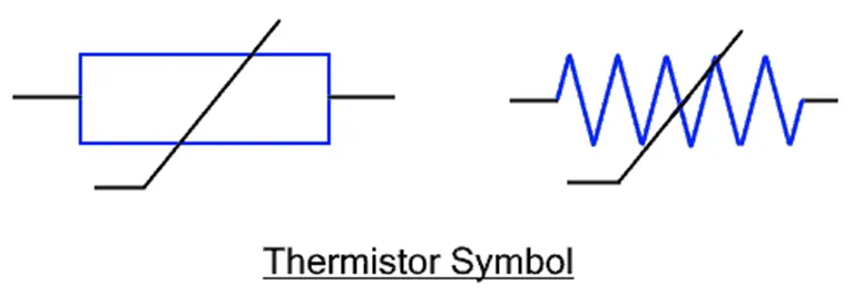
Symbol:
Applications:
- Digital thermometers (thermostats)
- Automotive applications (to measure oil and coolant temperatures in cars & trucks)
- Household appliances (like microwaves, fridges, and ovens)
- Circuit protection (i.e. surge protection)
- Rechargeable batteries
-
Working principle:
- The working principle of a thermistor is that its resistance is dependent on its temperature. We can measure the resistance of a thermistor using an ohmmeter.
- How much the resistance changes depends on the type of material used in the thermistor. The relationship between a thermistor’s temperature and resistance is non-linear. A typical thermistor graph is shown below:
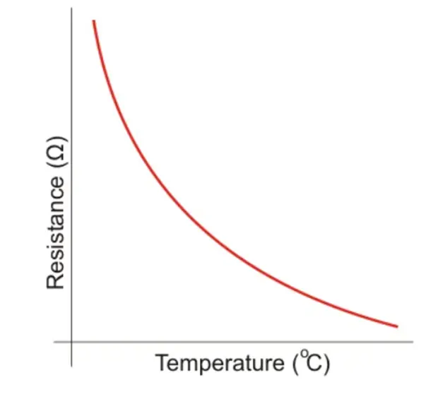
Here x-axis contain temperature
y-axis contain resistance
Thermistor:
Given inputs:
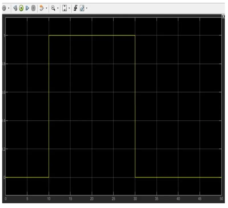
Temperature source: 20 centigrade 0 to 10 seconds, 27 centigrade from 10 to 30 seconds,23 centigrade from 0 to 50 seconds
Fan conditions: On if the temperature above 25 centigrade ,OFF otherwise
Simulink Model:
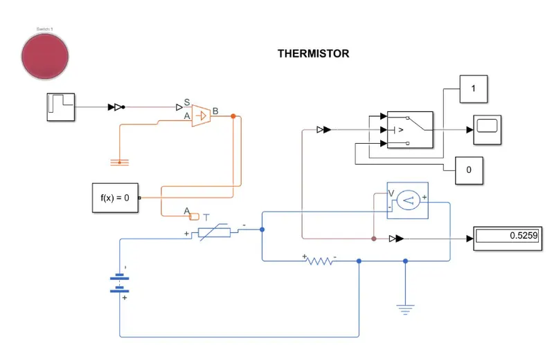 Simulink Model Explanation:
- Signal Builder block is uded to input the values as per given conditions:
. At point1, time=0 seconds, Temperature=293k
. At point2, time=10 seconds, Temperature=293k
. At point3, time=10 seconds, Temperature=300k
. At point4, time=30 seconds, Temperature=300k
. At point5, time=30 seconds, Temperature=296k
. At point6 , Time=50 Seconds, Temperature=296k
- Controlled Temperature source represents an represents an Ideal source of thermal energy, that can maintain a controlled temperature difference regardless of the heat flow rate. The temperature difference is Set by the physical signal port S.
- Thermistor is a type resistor whose resistance is based upon temperature.
- A linear resistor is used in order to control the amount of current from the battery.
- The voltage sensor is used to convert the voltage measured between two points into a physical signal.
- Voltage Source which represents dc or ac
- Electrical reference block is given
- Solver Configuration: Each physical network Configuration:
Each Physical network represented by a connected simcape blocks requiresSolver Setting information for simulation.
-
Thermistor wave forms: