Project
Aim:
To carry out a system –level simulation of a Baja ATV.
Objectives:
- Analyse all components and understand the relation and flow between the blocks.
- Understand the different types of ways to model this BAJA ATV.
An ATV is a small motor with three or for low – presser tires designed for se on various types of terrain. Recreational acitivities in deserts are usually carried out in ATVS. This project is in reference to one of the types of ATVS used in BAJA SAE competitions.
Study#1a: BAJA ATV with CTV
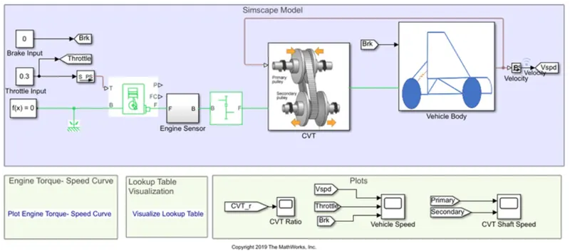
From this model, the components present are:
Brake and throttle input signal:
- No break is provie.
- A constant throttle of 0.3 for the first 20 seconds, and full throttle of 1 for the remainning.
- These two parameters are fe into the engine.
Generic engine:
- The engine uses a programmed realationship between speed and torqe, Modulated by the throttle Signal. The throttle input is seen above and the speed-torqe data points are extracted from the graph shown below and fed intothe enginethrough creation of column vectors in MATLAB.
- The Simpe gear between engine an the CVT gear box is to slow down the engine rpm before it isfe to the CVT. An appropriate gear ratio needs to be selected so that over or Under-revving is
Not an issue.
Continuously Variable Transmission:
- As evident in the meia above , two cone-shaped pulleys connected by a Steel or composite belt, Whose diamters are continuously variable, Work Together to provide infinite gear ratios.
- Optimizing engine speed in a variety o road conditions, according
To the Speed and torqe requirments of the terrain.
CVT subsystem block:
- The input and output shaft inertia reresents Primary Pully, and secondary Pulley respectively.
- The variable ratio gear block Represents the multile gears of the CVT, with the gear ratio input given to port R
- Two rational motion sensors are for tracking the angular velocities of the Pulleys.
Vehicle body Subsystem Block:
- .The Vehicle Body accounts for body mass, aerodynamic drag, road incline, and weight distribution between axles due to acceleration and road profile.
- .The Double-Shoe Brake is to apply brakes to the rear wheels. With this Component, Two brake bloks are applied at opposite ends of thedrum.this prevents an unbalnced fore fro acting on the shaft and bearing connecting the drum to the wheel, which would be the case with a single –shoe brake.
Vehicle speed output based on throttle and brake signals:
- These is constant acceleration at throttle of 0.3 from 0 to 20 seconds.
- After 20 seconds the car accelerates untill peak velocity as throttle hits a max value of 1.
CVT Shaft Speed output based on CTV gear ratio input:
- The CVT gear ratio input is above 1 throughout, Which is why we see a lower secondary RPM than primary, because the output shaft will rotate slower to provi more torqe to the wheels.
Varying CVT gear ratio:
- As soon as CVT gear ration falls below, the secondary RPM as the velocity of the vehicle also increases with the Redction in torque.
Study #1b: BAJA ATV with CVT and Dashboard:
- The only difference between study #1a and #1b is that the is that the throttle and brake inputs are given via graphical representation blocks while the simulation is running for an indefinite period. This allows us To input various Scenarios.
Study #2: BAJA ATV with Lookup table:
- The only difference with this study is that the CVT gear ratio is not ed via a single builder , Bt instea via a lookup table.
- This lookup table is dat regarding the realtion between CVT gear ratio and vehicle speed, which is incorporated through a simple Matlab script.
vv
Aim:
To carry out a system –level simulation of a Baja ATV.
Objectives:
- Analyse all components and understand the relation and flow between the blocks.
- Understand the different types of ways to model this BAJA ATV.
An ATV is a small motor with three or for low – presser tires designed for se on various types of terrain. Recreational acitivities in deserts are usually carried out in ATVS. This project is in reference to one of the types of ATVS used in BAJA SAE competitions.
Study#1a: BAJA ATV with CTV
From this model, the components present are:
Brake and throttle input signal:
- No break is provie.
- A constant throttle of 0.3 for the first 20 seconds, and full throttle of 1 for the remainning.
- These two parameters are fe into the engine.
Generic engine:
- The engine uses a programmed realationship between speed and torqe, Modulated by the throttle Signal. The throttle input is seen above and the speed-torqe data points are extracted from the graph shown below and fed intothe enginethrough creation of column vectors in MATLAB.
- The Simpe gear between engine an the CVT gear box is to slow down the engine rpm before it isfe to the CVT. An appropriate gear ratio needs to be selected so that over or Under-revving is
Not an issue.
Continuously Variable Transmission:
- As evident in the meia above , two cone-shaped pulleys connected by a Steel or composite belt, Whose diamters are continuously variable, Work Together to provide infinite gear ratios.
- Optimizing engine speed in a variety o road conditions, according
To the Speed and torqe requirments of the terrain.
CVT subsystem block:
- The input and output shaft inertia reresents Primary Pully, and secondary Pulley respectively.
- The variable ratio gear block Represents the multile gears of the CVT, with the gear ratio input given to port R
- Two rational motion sensors are for tracking the angular velocities of the Pulleys.
Vehicle body Subsystem Block:
- .The Vehicle Body accounts for body mass, aerodynamic drag, road incline, and weight distribution between axles due to acceleration and road profile.
- .The Double-Shoe Brake is to apply brakes to the rear wheels. With this Component, Two brake bloks are applied at opposite ends of thedrum.this prevents an unbalnced fore fro acting on the shaft and bearing connecting the drum to the wheel, which would be the case with a single –shoe brake.
Vehicle speed output based on throttle and brake signals:
- These is constant acceleration at throttle of 0.3 from 0 to 20 seconds.
- After 20 seconds the car accelerates untill peak velocity as throttle hits a max value of 1.
CVT Shaft Speed output based on CTV gear ratio input:
- The CVT gear ratio input is above 1 throughout, Which is why we see a lower secondary RPM than primary, because the output shaft will rotate slower to provi more torqe to the wheels.
Varying CVT gear ratio:
- As soon as CVT gear ration falls below, the secondary RPM as the velocity of the vehicle also increases with the Redction in torque.
Study #1b: BAJA ATV with CVT and Dashboard:
- The only difference between study #1a and #1b is that the is that the throttle and brake inputs are given via graphical representation blocks while the simulation is running for an indefinite period. This allows us To input various Scenarios.
Study #2: BAJA ATV with Lookup table:
- The only difference with this study is that the CVT gear ratio is not ed via a single builder , Bt instea via a lookup table.
- This lookup table is dat regarding the realtion between CVT gear ratio and vehicle speed, which is incorporated through a simple Matlab script.
v
Aim:
To carry out a system –level simulation of a Baja ATV.
Objectives:
- Analyse all components and understand the relation and flow between the blocks.
- Understand the different types of ways to model this BAJA ATV.
An ATV is a small motor with three or for low – presser tires designed for se on various types of terrain. Recreational acitivities in deserts are usually carried out in ATVS. This project is in reference to one of the types of ATVS used in BAJA SAE competitions.
Study#1a: BAJA ATV with CTV
From this model, the components present are:
Brake and throttle input signal:
- No break is provie.
- A constant throttle of 0.3 for the first 20 seconds, and full throttle of 1 for the remainning.
- These two parameters are fe into the engine.
Generic engine:
- The engine uses a programmed realationship between speed and torqe, Modulated by the throttle Signal. The throttle input is seen above and the speed-torqe data points are extracted from the graph shown below and fed intothe enginethrough creation of column vectors in MATLAB.
- The Simpe gear between engine an the CVT gear box is to slow down the engine rpm before it isfe to the CVT. An appropriate gear ratio needs to be selected so that over or Under-revving is
Not an issue.
Continuously Variable Transmission:
- As evident in the meia above , two cone-shaped pulleys connected by a Steel or composite belt, Whose diamters are continuously variable, Work Together to provide infinite gear ratios.
- Optimizing engine speed in a variety o road conditions, according
To the Speed and torqe requirments of the terrain.
CVT subsystem block:
- The input and output shaft inertia reresents Primary Pully, and secondary Pulley respectively.
- The variable ratio gear block Represents the multile gears of the CVT, with the gear ratio input given to port R
- Two rational motion sensors are for tracking the angular velocities of the Pulleys.
Vehicle body Subsystem Block:
- .The Vehicle Body accounts for body mass, aerodynamic drag, road incline, and weight distribution between axles due to acceleration and road profile.
- .The Double-Shoe Brake is to apply brakes to the rear wheels. With this Component, Two brake bloks are applied at opposite ends of thedrum.this prevents an unbalnced fore fro acting on the shaft and bearing connecting the drum to the wheel, which would be the case with a single –shoe brake.
Vehicle speed output based on throttle and brake signals:
- These is constant acceleration at throttle of 0.3 from 0 to 20 seconds.
- After 20 seconds the car accelerates untill peak velocity as throttle hits a max value of 1.
CVT Shaft Speed output based on CTV gear ratio input:
- The CVT gear ratio input is above 1 throughout, Which is why we see a lower secondary RPM than primary, because the output shaft will rotate slower to provi more torqe to the wheels.
Varying CVT gear ratio:
- As soon as CVT gear ration falls below, the secondary RPM as the velocity of the vehicle also increases with the Redction in torque.
Study #1b: BAJA ATV with CVT and Dashboard:
- The only difference between study #1a and #1b is that the is that the throttle and brake inputs are given via graphical representation blocks while the simulation is running for an indefinite period. This allows us To input various Scenarios.
Study #2: BAJA ATV with Lookup table:
- The only difference with this study is that the CVT gear ratio is not ed via a single builder , Bt instea via a lookup table.
- This lookup table is dat regarding the realtion between CVT gear ratio and vehicle speed, which is incorporated through a simple Matlab script.
v
Aim:
To carry out a system –level simulation of a Baja ATV.
Objectives:
- Analyse all components and understand the relation and flow between the blocks.
- Understand the different types of ways to model this BAJA ATV.
An ATV is a small motor with three or for low – presser tires designed for se on various types of terrain. Recreational acitivities in deserts are usually carried out in ATVS. This project is in reference to one of the types of ATVS used in BAJA SAE competitions.
Study#1a: BAJA ATV with CTV
From this model, the components present are:
Brake and throttle input signal:
- No break is provie.
- A constant throttle of 0.3 for the first 20 seconds, and full throttle of 1 for the remainning.
- These two parameters are fe into the engine.
Generic engine:
- The engine uses a programmed realationship between speed and torqe, Modulated by the throttle Signal. The throttle input is seen above and the speed-torqe data points are extracted from the graph shown below and fed intothe enginethrough creation of column vectors in MATLAB.
- The Simpe gear between engine an the CVT gear box is to slow down the engine rpm before it isfe to the CVT. An appropriate gear ratio needs to be selected so that over or Under-revving is
Not an issue.
Continuously Variable Transmission:
- As evident in the meia above , two cone-shaped pulleys connected by a Steel or composite belt, Whose diamters are continuously variable, Work Together to provide infinite gear ratios.
- Optimizing engine speed in a variety o road conditions, according
To the Speed and torqe requirments of the terrain.
CVT subsystem block:
- The input and output shaft inertia reresents Primary Pully, and secondary Pulley respectively.
- The variable ratio gear block Represents the multile gears of the CVT, with the gear ratio input given to port R
- Two rational motion sensors are for tracking the angular velocities of the Pulleys.
Vehicle body Subsystem Block:
- .The Vehicle Body accounts for body mass, aerodynamic drag, road incline, and weight distribution between axles due to acceleration and road profile.
- .The Double-Shoe Brake is to apply brakes to the rear wheels. With this Component, Two brake bloks are applied at opposite ends of thedrum.this prevents an unbalnced fore fro acting on the shaft and bearing connecting the drum to the wheel, which would be the case with a single –shoe brake.
Vehicle speed output based on throttle and brake signals:
- These is constant acceleration at throttle of 0.3 from 0 to 20 seconds.
- After 20 seconds the car accelerates untill peak velocity as throttle hits a max value of 1.
CVT Shaft Speed output based on CTV gear ratio input:
- The CVT gear ratio input is above 1 throughout, Which is why we see a lower secondary RPM than primary, because the output shaft will rotate slower to provi more torqe to the wheels.
Varying CVT gear ratio:
- As soon as CVT gear ration falls below, the secondary RPM as the velocity of the vehicle also increases with the Redction in torque.
Study #1b: BAJA ATV with CVT and Dashboard:
- The only difference between study #1a and #1b is that the is that the throttle and brake inputs are given via graphical representation blocks while the simulation is running for an indefinite period. This allows us To input various Scenarios.
Study #2: BAJA ATV with Lookup table:
- The only difference with this study is that the CVT gear ratio is not ed via a single builder , Bt instea via a lookup table.
- This lookup table is dat regarding the realtion between CVT gear ratio and vehicle speed, which is incorporated through a simple Matlab script.
Aim:
To carry out a system –level simulation of a Baja ATV.
Objectives:
- Analyse all components and understand the relation and flow between the blocks.
- Understand the different types of ways to model this BAJA ATV.
An ATV is a small motor with three or for low – presser tires designed for se on various types of terrain. Recreational acitivities in deserts are usually carried out in ATVS. This project is in reference to one of the types of ATVS used in BAJA SAE competitions.
Study#1a: BAJA ATV with CTV
From this model, the components present are:
Brake and throttle input signal:
- No break is provie.
- A constant throttle of 0.3 for the first 20 seconds, and full throttle of 1 for the remainning.
- These two parameters are fe into the engine.
Generic engine:
- The engine uses a programmed realationship between speed and torqe, Modulated by the throttle Signal. The throttle input is seen above and the speed-torqe data points are extracted from the graph shown below and fed intothe enginethrough creation of column vectors in MATLAB.
- The Simpe gear between engine an the CVT gear box is to slow down the engine rpm before it isfe to the CVT. An appropriate gear ratio needs to be selected so that over or Under-revving is
Not an issue.
Continuously Variable Transmission:
- As evident in the meia above , two cone-shaped pulleys connected by a Steel or composite belt, Whose diamters are continuously variable, Work Together to provide infinite gear ratios.
- Optimizing engine speed in a variety o road conditions, according
To the Speed and torqe requirments of the terrain.
CVT subsystem block:
- The input and output shaft inertia reresents Primary Pully, and secondary Pulley respectively.
- The variable ratio gear block Represents the multile gears of the CVT, with the gear ratio input given to port R
- Two rational motion sensors are for tracking the angular velocities of the Pulleys.
Vehicle body Subsystem Block:
- .The Vehicle Body accounts for body mass, aerodynamic drag, road incline, and weight distribution between axles due to acceleration and road profile.
- .The Double-Shoe Brake is to apply brakes to the rear wheels. With this Component, Two brake bloks are applied at opposite ends of thedrum.this prevents an unbalnced fore fro acting on the shaft and bearing connecting the drum to the wheel, which would be the case with a single –shoe brake.
Vehicle speed output based on throttle and brake signals:
- These is constant acceleration at throttle of 0.3 from 0 to 20 seconds.
- After 20 seconds the car accelerates untill peak velocity as throttle hits a max value of 1.
CVT Shaft Speed output based on CTV gear ratio input:
- The CVT gear ratio input is above 1 throughout, Which is why we see a lower secondary RPM than primary, because the output shaft will rotate slower to provi more torqe to the wheels.
Varying CVT gear ratio:
- As soon as CVT gear ration falls below, the secondary RPM as the velocity of the vehicle also increases with the Redction in torque.
Study #1b: BAJA ATV with CVT and Dashboard:
- The only difference between study #1a and #1b is that the is that the throttle and brake inputs are given via graphical representation blocks while the simulation is running for an indefinite period. This allows us To input various Scenarios.
Study #2: BAJA ATV with Lookup table:
- The only difference with this study is that the CVT gear ratio is not ed via a single builder , Bt instea via a lookup table.
- This lookup table is dat regarding the realtion between CVT gear ratio and vehicle speed, which is incorporated through a simple Matlab script.
Aim:
To carry out a system –level simulation of a Baja ATV.
Objectives:
- Analyse all components and understand the relation and flow between the blocks.
- Understand the different types of ways to model this BAJA ATV.
An ATV is a small motor with three or for low – presser tires designed for se on various types of terrain. Recreational acitivities in deserts are usually carried out in ATVS. This project is in reference to one of the types of ATVS used in BAJA SAE competitions.
Study#1a: BAJA ATV with CTV
From this model, the components present are:
Brake and throttle input signal:
- No break is provie.
- A constant throttle of 0.3 for the first 20 seconds, and full throttle of 1 for the remainning.
- These two parameters are fe into the engine.
Generic engine:
- The engine uses a programmed realationship between speed and torqe, Modulated by the throttle Signal. The throttle input is seen above and the speed-torqe data points are extracted from the graph shown below and fed intothe enginethrough creation of column vectors in MATLAB.
- The Simpe gear between engine an the CVT gear box is to slow down the engine rpm before it isfe to the CVT. An appropriate gear ratio needs to be selected so that over or Under-revving is
Not an issue.
Continuously Variable Transmission:
- As evident in the meia above , two cone-shaped pulleys connected by a Steel or composite belt, Whose diamters are continuously variable, Work Together to provide infinite gear ratios.
- Optimizing engine speed in a variety o road conditions, according
To the Speed and torqe requirments of the terrain.
CVT subsystem block:
- The input and output shaft inertia reresents Primary Pully, and secondary Pulley respectively.
- The variable ratio gear block Represents the multile gears of the CVT, with the gear ratio input given to port R
- Two rational motion sensors are for tracking the angular velocities of the Pulleys.
Vehicle body Subsystem Block:
- .The Vehicle Body accounts for body mass, aerodynamic drag, road incline, and weight distribution between axles due to acceleration and road profile.
- .The Double-Shoe Brake is to apply brakes to the rear wheels. With this Component, Two brake bloks are applied at opposite ends of thedrum.this prevents an unbalnced fore fro acting on the shaft and bearing connecting the drum to the wheel, which would be the case with a single –shoe brake.
Vehicle speed output based on throttle and brake signals:
- These is constant acceleration at throttle of 0.3 from 0 to 20 seconds.
- After 20 seconds the car accelerates untill peak velocity as throttle hits a max value of 1.
CVT Shaft Speed output based on CTV gear ratio input:
- The CVT gear ratio input is above 1 throughout, Which is why we see a lower secondary RPM than primary, because the output shaft will rotate slower to provi more torqe to the wheels.
Varying CVT gear ratio:
- As soon as CVT gear ration falls below, the secondary RPM as the velocity of the vehicle also increases with the Redction in torque.
Study #1b: BAJA ATV with CVT and Dashboard:
- The only difference between study #1a and #1b is that the is that the throttle and brake inputs are given via graphical representation blocks while the simulation is running for an indefinite period. This allows us To input various Scenarios.
Study #2: BAJA ATV with Lookup table:
- The only difference with this study is that the CVT gear ratio is not ed via a single builder , Bt instea via a lookup table.
- This lookup table is dat regarding the realtion between CVT gear ratio and vehicle speed, which is incorporated through a simple Matlab script.
Aim:
To carry out a system –level simulation of a Baja ATV.
Objectives:
- Analyse all components and understand the relation and flow between the blocks.
- Understand the different types of ways to model this BAJA ATV.
An ATV is a small motor with three or for low – presser tires designed for se on various types of terrain. Recreational acitivities in deserts are usually carried out in ATVS. This project is in reference to one of the types of ATVS used in BAJA SAE competitions.
Study#1a: BAJA ATV with CTV
From this model, the components present are:
Brake and throttle input signal:
- No break is provie.
- A constant throttle of 0.3 for the first 20 seconds, and full throttle of 1 for the remainning.
- These two parameters are fe into the engine.
Generic engine:
- The engine uses a programmed realationship between speed and torqe, Modulated by the throttle Signal. The throttle input is seen above and the speed-torqe data points are extracted from the graph shown below and fed intothe enginethrough creation of column vectors in MATLAB.
- The Simpe gear between engine an the CVT gear box is to slow down the engine rpm before it isfe to the CVT. An appropriate gear ratio needs to be selected so that over or Under-revving is
Not an issue.
Continuously Variable Transmission:
- As evident in the meia above , two cone-shaped pulleys connected by a Steel or composite belt, Whose diamters are continuously variable, Work Together to provide infinite gear ratios.
- Optimizing engine speed in a variety o road conditions, according
To the Speed and torqe requirments of the terrain.
CVT subsystem block:
- The input and output shaft inertia reresents Primary Pully, and secondary Pulley respectively.
- The variable ratio gear block Represents the multile gears of the CVT, with the gear ratio input given to port R
- Two rational motion sensors are for tracking the angular velocities of the Pulleys.
Vehicle body Subsystem Block:
- .The Vehicle Body accounts for body mass, aerodynamic drag, road incline, and weight distribution between axles due to acceleration and road profile.
- .The Double-Shoe Brake is to apply brakes to the rear wheels. With this Component, Two brake bloks are applied at opposite ends of thedrum.this prevents an unbalnced fore fro acting on the shaft and bearing connecting the drum to the wheel, which would be the case with a single –shoe brake.
Vehicle speed output based on throttle and brake signals:
- These is constant acceleration at throttle of 0.3 from 0 to 20 seconds.
- After 20 seconds the car accelerates untill peak velocity as throttle hits a max value of 1.
CVT Shaft Speed output based on CTV gear ratio input:
- The CVT gear ratio input is above 1 throughout, Which is why we see a lower secondary RPM than primary, because the output shaft will rotate slower to provi more torqe to the wheels.
Varying CVT gear ratio:
- As soon as CVT gear ration falls below, the secondary RPM as the velocity of the vehicle also increases with the Redction in torque.
Study #1b: BAJA ATV with CVT and Dashboard:
- The only difference between study #1a and #1b is that the is that the throttle and brake inputs are given via graphical representation blocks while the simulation is running for an indefinite period. This allows us To input various Scenarios.
Study #2: BAJA ATV with Lookup table:
- The only difference with this study is that the CVT gear ratio is not ed via a single builder , Bt instea via a lookup table.
- This lookup table is dat regarding the realtion between CVT gear ratio and vehicle speed, which is incorporated through a simple Matlab script.
Aim:
To carry out a system –level simulation of a Baja ATV.
Objectives:
- Analyse all components and understand the relation and flow between the blocks.
- Understand the different types of ways to model this BAJA ATV.
An ATV is a small motor with three or for low – presser tires designed for se on various types of terrain. Recreational acitivities in deserts are usually carried out in ATVS. This project is in reference to one of the types of ATVS used in BAJA SAE competitions.
Study#1a: BAJA ATV with CTV
From this model, the components present are:
Brake and throttle input signal:
- No break is provie.
- A constant throttle of 0.3 for the first 20 seconds, and full throttle of 1 for the remainning.
- These two parameters are fe into the engine.
Generic engine:
- The engine uses a programmed realationship between speed and torqe, Modulated by the throttle Signal. The throttle input is seen above and the speed-torqe data points are extracted from the graph shown below and fed intothe enginethrough creation of column vectors in MATLAB.
- The Simpe gear between engine an the CVT gear box is to slow down the engine rpm before it isfe to the CVT. An appropriate gear ratio needs to be selected so that over or Under-revving is
Not an issue.
Continuously Variable Transmission:
- As evident in the meia above , two cone-shaped pulleys connected by a Steel or composite belt, Whose diamters are continuously variable, Work Together to provide infinite gear ratios.
- Optimizing engine speed in a variety o road conditions, according
To the Speed and torqe requirments of the terrain.
CVT subsystem block:
- The input and output shaft inertia reresents Primary Pully, and secondary Pulley respectively.
- The variable ratio gear block Represents the multile gears of the CVT, with the gear ratio input given to port R
- Two rational motion sensors are for tracking the angular velocities of the Pulleys.
Vehicle body Subsystem Block:
- .The Vehicle Body accounts for body mass, aerodynamic drag, road incline, and weight distribution between axles due to acceleration and road profile.
- .The Double-Shoe Brake is to apply brakes to the rear wheels. With this Component, Two brake bloks are applied at opposite ends of thedrum.this prevents an unbalnced fore fro acting on the shaft and bearing connecting the drum to the wheel, which would be the case with a single –shoe brake.
Vehicle speed output based on throttle and brake signals:
- These is constant acceleration at throttle of 0.3 from 0 to 20 seconds.
- After 20 seconds the car accelerates untill peak velocity as throttle hits a max value of 1.
CVT Shaft Speed output based on CTV gear ratio input:
- The CVT gear ratio input is above 1 throughout, Which is why we see a lower secondary RPM than primary, because the output shaft will rotate slower to provi more torqe to the wheels.
Varying CVT gear ratio:
- As soon as CVT gear ration falls below, the secondary RPM as the velocity of the vehicle also increases with the Redction in torque.
Study #1b: BAJA ATV with CVT and Dashboard:
- The only difference between study #1a and #1b is that the is that the throttle and brake inputs are given via graphical representation blocks while the simulation is running for an indefinite period. This allows us To input various Scenarios.
Study #2: BAJA ATV with Lookup table:
- The only difference with this study is that the CVT gear ratio is not ed via a single builder , Bt instea via a lookup table.
- This lookup table is dat regarding the realtion between CVT gear ratio and vehicle speed, which is incorporated through a simple Matlab script.
Aim:
To carry out a system –level simulation of a Baja ATV.
Objectives:
- Analyse all components and understand the relation and flow between the blocks.
- Understand the different types of ways to model this BAJA ATV.
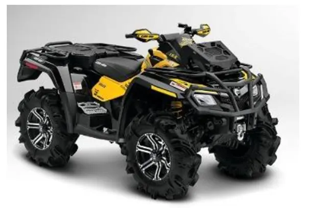
An ATV is a small motor with three or for low – presser tires designed for se on various types of terrain. Recreational acitivities in deserts are usually carried out in ATVS. This project is in reference to one of the types of ATVS used in BAJA SAE competitions.
Study#1a: BAJA ATV with CTV
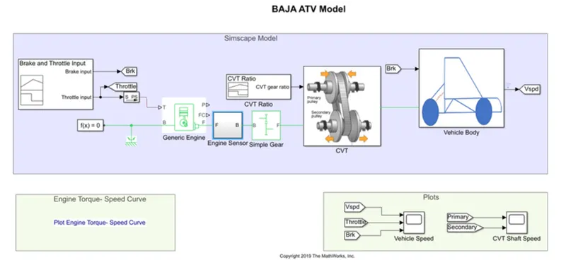
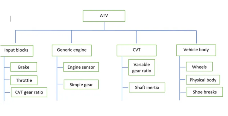
From this model, the components present are:
Brake and throttle input signal:
- No break is provie.
- A constant throttle of 0.3 for the first 20 seconds, and full throttle of 1 for the remainning.
- These two parameters are fe into the engine.
Generic engine
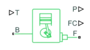
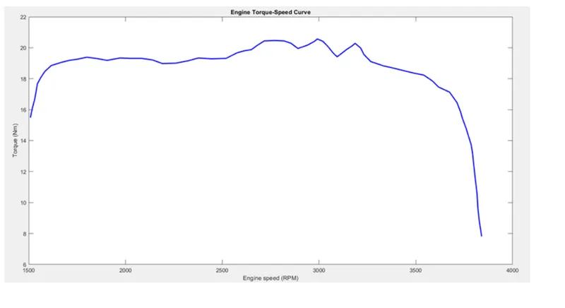
- The engine uses a programmed realationship between speed and torqe, Modulated by the throttle Signal. The throttle input is seen above and the speed-torqe data points are extracted from the graph shown below and fed intothe enginethrough creation of column vectors in MATLAB.
- The Simpe gear between engine an the CVT gear box is to slow down the engine rpm before it isfe to the CVT. An appropriate gear ratio needs to be selected so that over or Under-revving is Not an issue.
Continuously Variable Transmission:
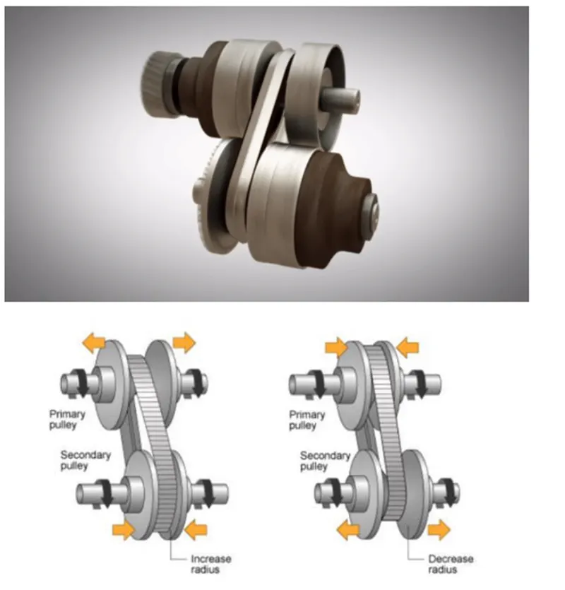
- As evident in the meia above , two cone-shaped pulleys connected by a Steel or composite belt, Whose diamters are continuously variable, Work Together to provide infinite gear ratios.
- Optimizing engine speed in a variety o road conditions, according To the Speed and torqe requirments of the terrain.
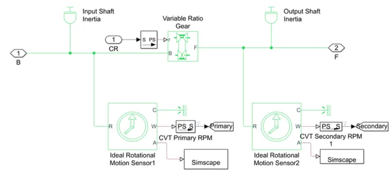
CVT subsystem block:
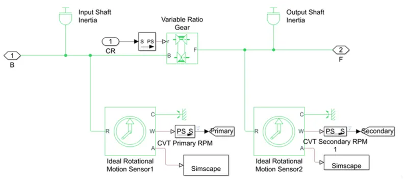
- The input and output shaft inertia reresents Primary Pully, and secondary Pulley respectively.
- The variable ratio gear block Represents the multile gears of the CVT, with the gear ratio input given to port Two rational motion sensors are for tracking the angular velocities of the Pulleys.
Vehicle body Subsystem Block:
- The Vehicle Body accounts for body mass, aerodynamic drag, road incline, and weight distribution between axles due to acceleration and road profile.
. The Double-Shoe Brake is to apply brakes to the rear wheels. With this Component, Two brake bloks are applied at opposite ends of thedrum.this prevents an unbalnced fore fro acting on the shaft and bearing connecting the drum to the wheel, which would be the case with a single –shoe brake.
Vehicle speed output based on throttle and brake signals:
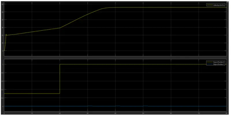
- These is constant acceleration at throttle of 0.3 from 0 to 20 seconds.
- After 20 seconds the car accelerates untill peak velocity as throttle hits a max value of 1.
CVT Shaft Speed output based on CTV gear ratio input:
 v
v
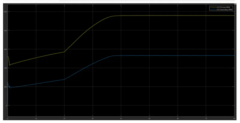
The CVT gear ratio input is above 1 throughout, Which is why we see a lower secondary RPM than primary, because the output shaft will rotate slower to provi more torqe to the wheels.
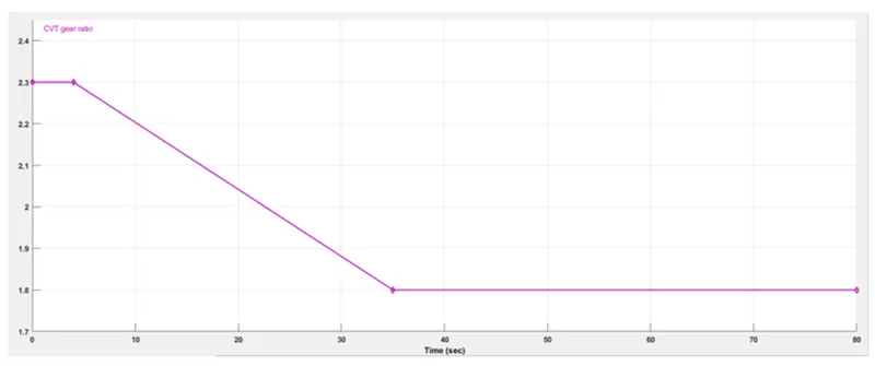
Varying CVT gear ratio:
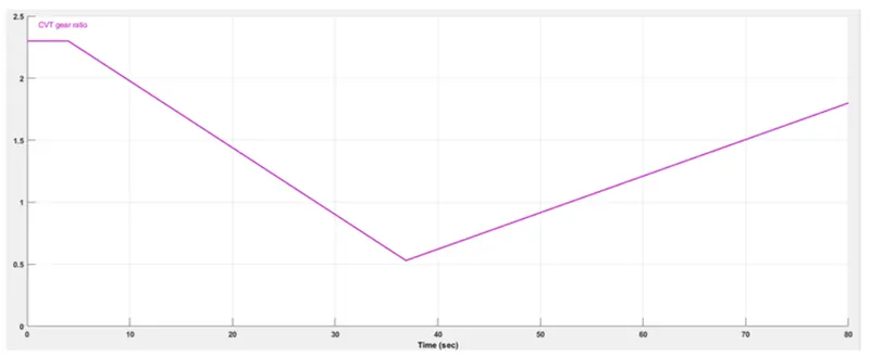
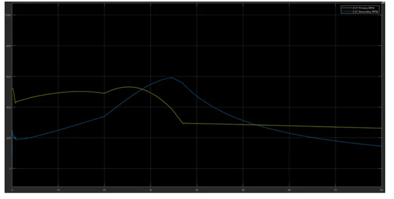
As soon as CVT gear ration falls below, the secondary RPM as the velocity of the vehicle also increases with the Redction in torque.
Study #1b: BAJA ATV with CVT and Dashboard:
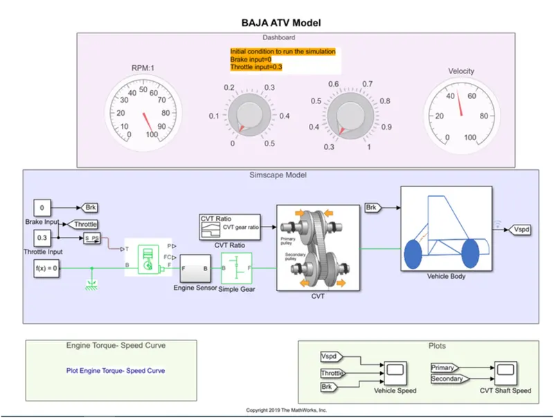
The only difference between study #1a and #1b is that the is that the throttle and brake inputs are given via graphical representation blocks while the simulation is running for an indefinite period. This allows us To input various Scenarios
Study #2: BAJA ATV with Lookup table:
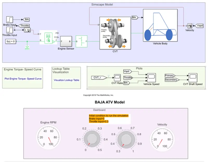
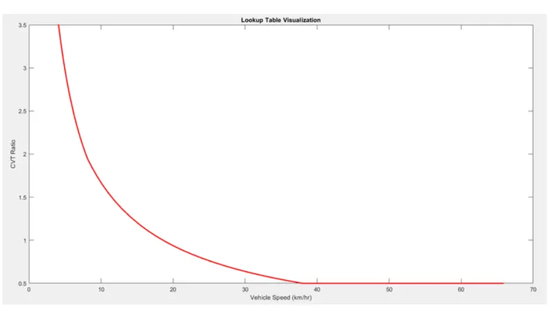
- The only difference with this study is that the CVT gear ratio is not ed via a single builder , Bt instea via a lookup table.
- This lookup table is dat regarding the realtion between CVT gear ratio and vehicle speed, which is incorporated through a simple Matlab script.