Week -2
Explanation,
Doorbell,
The most widely used form is the interrupter bell, which is the mechanical bell that produces a continous sound when current is applied.the bell is often in the shape of cup or half sphere by a spring load arm with a metal ball at the end called as clapper,actuated by solenoid.
Solenoid,
It is a device comprised of a coil of wire,housing and a moveable plunger,when an electric current is introduced a magnetic field form around the coil, a solenoid converts electric energy into mechanical work.
BLOCK USED
1.pluse generator-its block generates square wave pulses at regular intervals.the block waveform parameters,amplitude,pluse width,period,phase delay,determine the output wave form.
2.simulink-PS converter-it converts input simulink signal into a physical signal.
3.Switch-it controlled by external physical signal,if the external physical signal PS is the greater than the value soecified in the threshold parameter.
4.Battery-it implements a generic dynamic model that represents the most popular types of rechargeable batteries.
5.Solenoid- it represents the electrical characteristics and generated force for the solenoid.
6.Solver configuration- Each physical network represents by a connected simscape block diagram requires solver settings information for simulation.
7.Ideal translation motion sensor - it represents a device that converts an across variable measured b/w 2 mechanical translational nodes into a contril signal position.
8.Scope - Display signals generated during simulation in simple word display graph with respect to time.
MODEL,
* First we take the solenoid from the libroury browser then one end of the solenoid connected the battery it also connected to the electrical reference,another end of the solenoid connected to switch,the switch also connected to plus generator by usind simulink-Ps convetror and PS- simulink convertor.
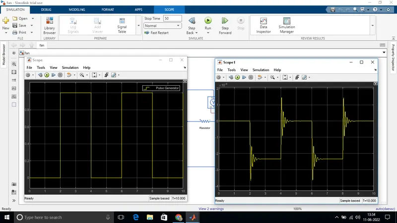
* The pluse generator also connected to scope to display the graphical diagram.The another end of the solenoid is connected into ideal translatioal motion sensor it conneced to mechanical translational reference,P is connected in the scope by using simulate-Ps convetor solver configuration is added to scope.
2.Thermistor Theory,
A thermistor is a resistance thermometer or a resistor whose resistance is dependent on temperature. the term is a combination of thermal and resistor.
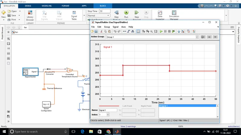
Here the input is fed through the block'signl builder' the inputs data is given based on the initial conditions provided in the clallenge,
TEMPS,
Temp 20 degree C from 0-10 sec-293K
Temp 27 degree C from 10-30 sec-300K
Temp 23 degree C from 30-50 sec-296K
As per the condition the input of the signal builder is incorporated.
Before this signal is been fed into the controlled temp sourse the setting of the 'simulink physical signal convertor'have to be modified, in the input handling,the filter input and derivative has to be selected instead of the signal this is because here we use two heat sourse namely'controlled temperature source'.
The positive side of the thermistor is connected to the positive terminal of the battery and the negative side of the terminal is connected to the current sensor. this is followed by electrical resistance.
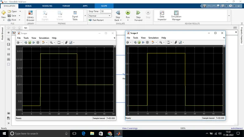
The value from the current sensor is converted into the simulink signal using the convertor.the value obtained is displayed in the display block. This just to give the threshold value inside the switch which has 2 ouput based on 2 conditions if he value is above the threshold value of the output will be 1 and the value is below the threshold value of the out put will be 0.the final output is recorded in the scope.
So based on the given condition the fan should work only in the time period of 0 to 30 sec which is exactly depicted in the graph shoen.