Week -2
AIM:
- To make a simulink model of doorbell using solenoid bolck.
- to make a simulink model using a thermistor to sense the temperature of a heater and turn on and turn off the faan.
OBJECTIVES:
- For the model of doorbell using solenoid block we have to create a situation where the switch is closed for 2 secs. and then released.and observe the possition of the plunger.
- For the model to use a thermistor to sence the temperature of heater and turn on and turn off the fan as per the below conditions .
Temperature source:
20deg from 0 to 10 sec.
27deg from 10 to 30 sec.
23deg from 30 to 50 sec.
Fan condition:
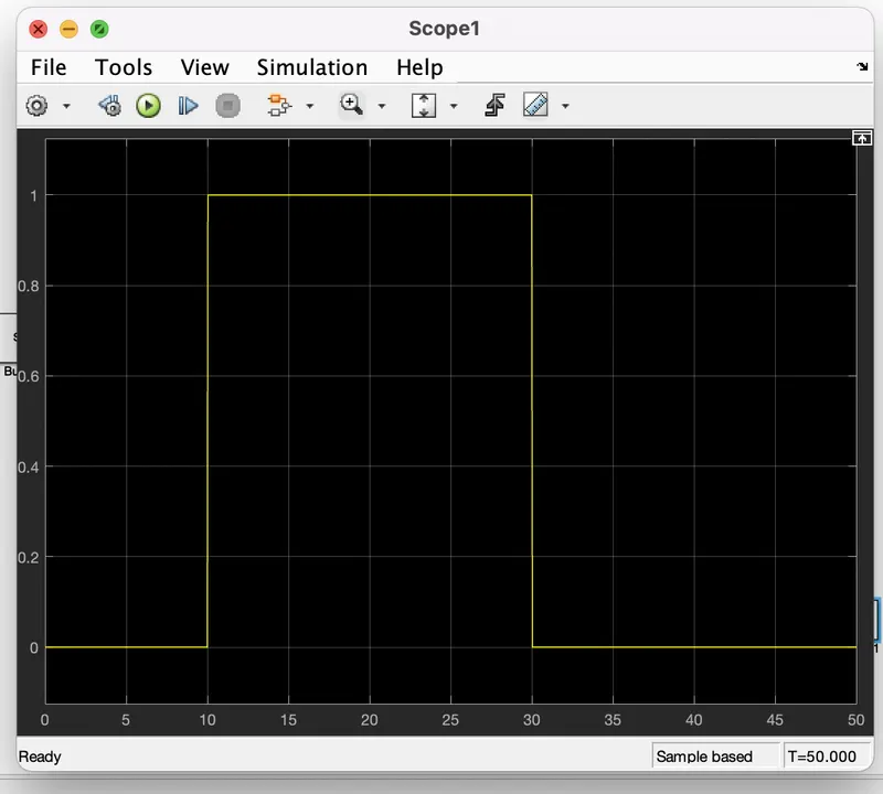
ON if the temperature is above 25deg ,OFF otherwise.
THEORY:
solenoid:
A solenoid is a type of electromagnet formed by a helical coil of wire whose length is substantially greater than its diameter, which generates a controlled magnetic field. The coil can produce a uniform magnetic field in a volume of space when an electric current is passed through it. The term solenoid was coined in 1823 by André-Marie Ampère.
The helical coil of a solenoid does not necessarily need to revolve around a straight-line axis; for example, William Sturgeon's electromagnet of 1824 consisted of a solenoid bent into a horseshoe shape (not unlike an arc spring).
Solenoids provide magnetic focusing of electrons in vacuums, notably in television camera tubes such as vidicons and image orthicons. Electrons take helical paths within the magnetic field. These solenoids, focus coils, surround nearly the whole length of the tube.
In engineering, the term "solenoid" refers not only to the electromagnet but to a complete apparatus providing an actuator that converts electrical energy to mechanical energy.
The basic components used to setup a simple doorbell circuit are :
- battery
- switch
- solenoid
- a bell with a plunger
THERMISTOR:
A thermistor is a type of resistor whose resistance is strongly dependent on temperature, more so than in standard resistors. The word thermistor is a portmanteau of thermal and resistor.
Thermistors are divided based on their conduction model. Negative Temperature Coefficient (NTC) thermistors have less resistance at higher temperatures, while Positive Temperature Coefficient (PTC) thermistors have more resistance at higher temperatures. Hence, a PTC thermistor's resistance is directly proportional to temperature.
NTC thermistor are widely used as inrush current limiters, temperature sensors, while PTC thermistors are used as self-resetting overcurrent protectors, and self-regulating heating elements. An operational temperature range of a thermistor is dependent on the probe type and is typically between −100 ⁰C and 300 ⁰C
The basic components used to setup a simple cooling fan circuit are :
- Battery
- thermistor
- Fan
- Transistor
- Resistor
MODEL:

EXPLANATION:
- From the above governing circuit of a doorbell, we know that we need a switch ,battery and plunger .
- so,in order to get all these components in simulink model we have to take the blocks which perform the same funtion as the above device.
- now first a 'Solenoid inthe model,then we take a 'Battery block' from the library browser.
- Then this 'Solinoid block' and 'Battery block' is connected through the positive and negative terminals.
- A 'switch block' is used between the 'solenoid block' and 'battery block'.
- now for the switch to operate we must provide a physical signal through 'ps' port in the 'switch block'. the provided physical signal must be greater than the threshold of the switch , for the switch to be closed or else it will be opened.
- now this whole battery ,switch and solenoid path is connected to 'Electrical Refrence block ' which represents the earthing of hte circuit .the 'Electrical Reference block' should be connected with the negative terminal of the 'Battery block'.
- Then in the 'solenoid block','R' and 'C'are two variables which represents the plunger and fixed point respecteviy.
- Now in the 'ideal Translation Motion sensor block',which ssence the poisition of the plunger in the 'Solenoid block' and gives the output.
- now in the 'ideal translation motion senspr block', the outputs are given as V andP which represent the velocity and the position of the plunger.since ,we need to observe only the position of the plunger ,we need the resultsfrom 'P'output.
- Now the 'C' in the 'Ideal translation motion sensor block' represents the mechanical translation conversion port which means that the mechanical process strats from 'R' and ends at 'C' and it again strats from 'R" and the cycle goes on.
- so 'C' in the 'Ideal translation motion sensor block' is connected to a 'mechanical translation Refrence block' which represents a fixed point where it is rigidly clamped in real time.
- similarly,'C' of the solenoid block is also connected to the same 'mechanical translation Refrence block' as fixed point for the solenoid.
- since we position the plunger as output from 'Ideal translation motion sensor block' we have connected the port 'P' to a'PS' simulink converter block ,where the physical values of the port 'P' are converted to simulink vallue which is connected to the 'scope block' for generating the graph of the change in the position of the plunger from port 'P' of 'Ideal translation motion sensor block'.
- now to provide a physical signal for operating the switch w have used the 'pluse generator block' which generator a continuous square pulse.
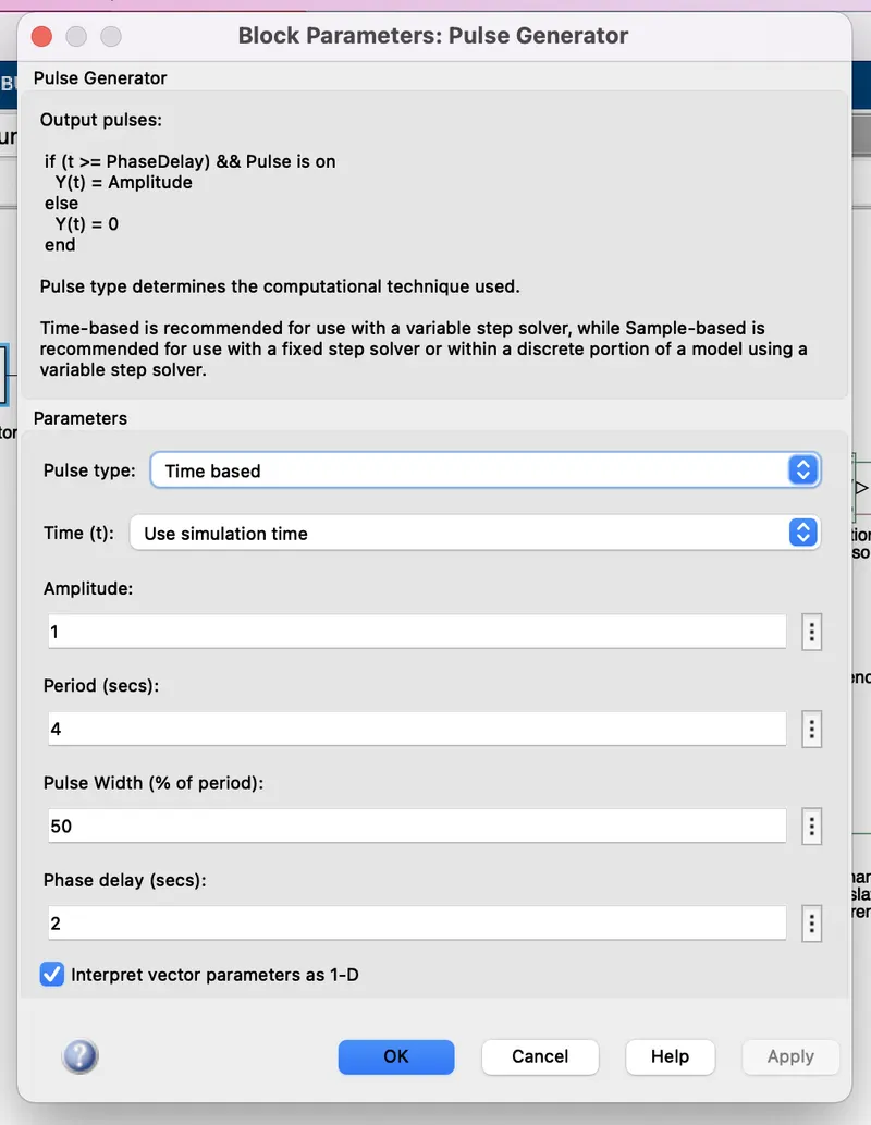
- From the above figure we can observe that we have given perriod value as '4' ,pluse width as '50', phase delay as '2' and amplitude by default is '1' we have not changed it. this means that initially the pulse will be zero and at 2sec the pluse width will half of periods, so for the next two sec. the pulse will be at ammplitude '1' only then it will again come down to 0 for next 2 secs thus completing the periods of 4 secs.
- From strating to ending of the pulse will take 4 secs of time period in which only for 2 secs the amplitude will be one and for rest of time it will be zero. so, after these 4secs period again the pulse will be generated and thus cycle continues.
- to this 'pulse' generator 'block' is connected to see hoe the pulse is generated .
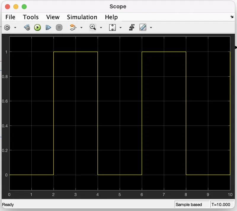
- As mentioned before ,the pulse has strated after 2secs, then for next 2 secs it has amplitude of '1' and then next 2secs the pulse is again zero .the pulse is strating from 2secs and ending at 6secs which nothing but a time period of 2 secs.
- Thus ,this represents that when amplitude is one , the switch will be closed and when it 0 the switch will be open.since our objective is only to see the change in position of plunger when switch is closed for 2 secs so that we have the amplitude as 1 for2 secs in the pulse generator by making the pulse width half of the period in the inputs for 'pulse' generation block.
- since the pulse that is coming from'pulse generator block' is a simulink value ,so to convert this value into physical value we have used 'simulink -ps converter block' ,since switch only takes phycical value as inputs
- As mentioned above the port 'p' of 'Ideal translation motion sensor block' is connected to another 'scope block' ,and a 'slover configuration block' is also connected to this path which generates equations and solves and whole model internally to give the results of the whole simulink model as output.
- Now run the model and doble click on the 'scope block', which is connected to 'Ideal translation motion sensor block' to get the results
- we will get above the graph as the result ehen we doble click on the 'scope block'.here x-axis represent time in secs,y-axis represents position of plunger in mm.
- From the above figure we can observe that the initial position of the plunger is at '5' as from the plunger generator block, a pulse generated at 2 ,so in the position of the plunger is also changing at time 2sec and time till which the pulse amplitude is '1' till that time plunger is also at same position after the change from intial position.
- Again ,as the amplitude of the pulse becomes 0,the plunger returns to initial position back again and as the pulse cycle goes on, plunger also changes it position and comes back to its initial position.
- we can also observe thet when there is a change in position of the plunger , there are some wave forms at the strat of changes in position. This is due to recoil of the spring ,each time when the plunger is moving .so to reduce this ,in the 'solinoid block' we can reduce the spring constant and increase the damping co-eficient.this will reduce the waves that are being formed and we will get a smooth graph.
- the above graph is asmoother graph than previous one .this is done by changing the valve of spring constant and damping in 'solenoid block'.
MODEL:
EXPLAIN:
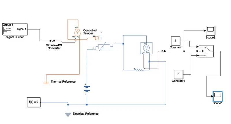
- TO create a simple cooling fan model using thermistor we need a thermistor ,battery,switch,scope,resistor, voltmeter,and basic components of the circuit we need in the simulink model.
- First to represent a thermistor ,a 'thermistor block' is taken and place inthe model.now to represent a battery,a 'battery block' is taken and the positive port of the block is connected to the positive port of the thermistor.
- now to represent a resistor ,a 'resistor block' is taken from the library browser and its positive port connected by a negative port of the thermistor.and the nagative port of the resistor is connected to the negative port of the battery,which is represents the earthing of the real time ciruit.
- now to represents a voltmeter a 'voltage block' is connected parallel to the 'resistor block' ,because to measure the voltage across the line,voltmeter should be always connected parallel to that component.
- thus , we have complete our simple circuit model, but we need some physical quantities to as signal for thermistor to work.
- In this case we need the fan to get ON and OFF at different temperature.so,to provide temperature ,we have used 'controlled temperature block' which only gives a specified temperature as output evan though heat flow is more.
- Now to give different temperature to this 'controlled temperature block' we need to send the temperature signals.to send these signals we have used a 'signal builder block, which allows use to send any type of signals as inputs
- We have to double click on the 'signle builder block' to set the signal according to our requirement.
- When we ioen the 'signle builder block'.as this dialogue box opens ,first we have to click on the 'signal' at the top and then select 'new' next select 'custom' option.Now it will ask to give values of y-axis and x-axis.since we know that at which times ,we need which temperature as mention in the strating ,we can give those values in an array in this box and then the above fig signals are generated.
- We can see that hoe different temperature are given at different time.so, thus we have create our signals and before connecting in to the 'controlled temperature block' we have to convert these signals into a physical value.so ,to do this we have used a 'simulink ps converter'.
- So now the port 'B' of 'controlled temperature block' is connected to port 'A' of 'controlled temperature block' is connected to the ' thermal reference block'.In 'controlled temperature block' a positive temperature difference causes the temperature at port B to be greater than the temperature at port 'A'.
- Now the output of the 'voltage sensor block' is connected to 'display block' first, and before connecting to the 'display block' a 'PS-Simulink Converter' is used to convert physical values to simulink values.
- Now when we run the simulation and double click on the 'display block' and we will get the voltage at 25 deg,using this information we can set condition for fan to ON and OFF.
- As mentioned in the objective fan should be ON when temperature is more than 25deg ,i.e.when the voltage is more than 5.665e-22 then fan should ON and when the voltage is below 5.665e-22 the fan should be OFF.
- This above logic used to ON and OFF the fan.To do this we have used a 'switch block' that routes the signals sccording to provided.
- the centre port of 'swicth block' is connected to output of 'PS simulink coverter' which gives the voltage values. the top port of the switch block is connected to a constant block of value 1 and bottom of the 'swicth block' is connected to another 'constant block' of value 0.
- the centre port of 'swicth block' is the condition input which means that when the value from 'voltage sensor block' is more than the threshold value in the 'swicth block' then it will pass the value 1 which we have specified in the top port of the 'swicth block' .if the voltage from 'voltage sensor block' is less than the threshold value in the 'swicth block'.here it acts like a transistor in a real time cicuit .
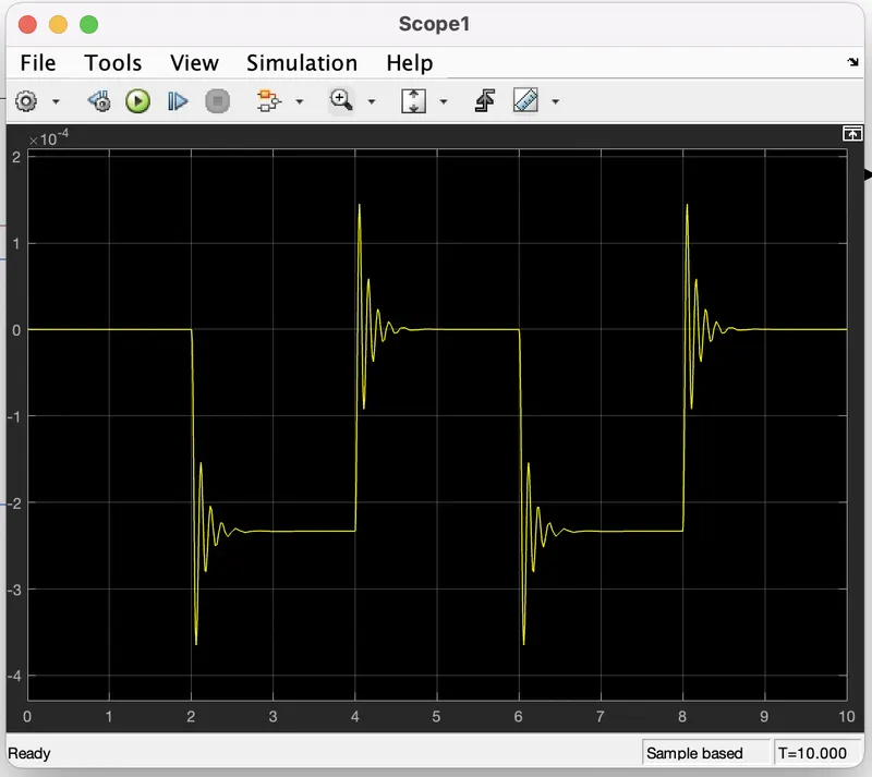
- to set the threshold value of 'swicth block' ,we have to double click on the 'swicth block' and then we can change the valve of threshold .since we want switch to be ON only when temperature is 300k so the threshold is given as 5.665e-22 the switch will give value 1 as output which means fan will be ON and when voltage get less than 5.665e-22 the switch will give value 0 as output which means fan will be OFF.
- Now the output of the 'swicth block' is connected to another port to get the results.
conclusion:
- Thus , both the objetive were achived successfully.
- similar approach can be used for simulating other physical devices using simulink.