Simulating Simulink Models - Electric Doorbell using solenoid and Thermistor controlled Fan
Aim: To make a simulink model for doorbell using solenoid and thermistor to sense a heater to control the fan.
Objectives:
1. Generate a simulink model of doorbell using solenoid block as per below conditions.
- Create a situation where the switch is closed for 2 seconds and then released.
2. Generate a simulink model of a thermistor to sense the temperature of a heater & turn on or turn off the fan as per below conditions.
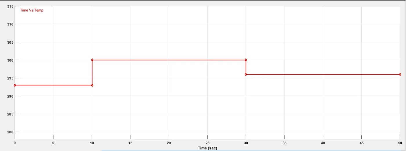
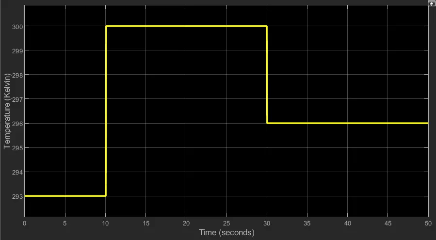
- Temperature source: 20 °C from 0 to 10 seconds, 27 °C from 10 to 30 seconds, 23 °C from 30 to 50 seconds
- Fan conditions: ON if the temperature above 25 °C, OFF otherwise
SIMULINK MODEL OF DOORBELL USING SOLENOID
Theory:
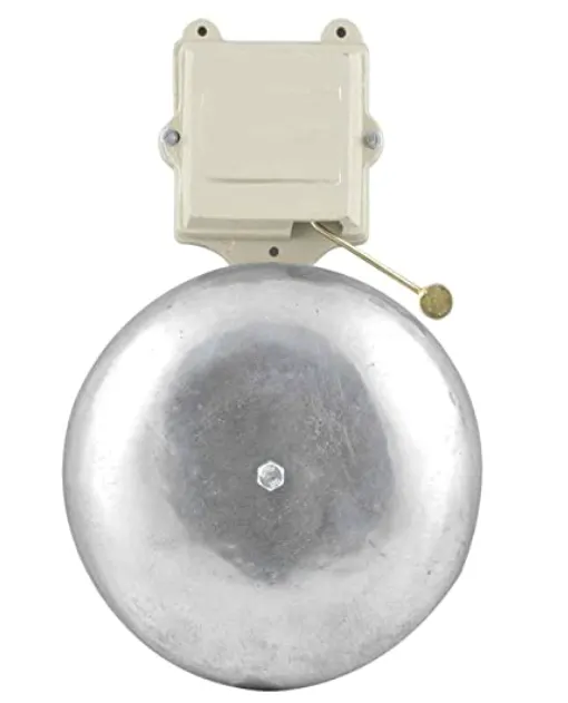
Doorbell:
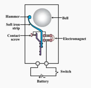
The heart of a doorbell is an electromagnet. Electromagnets are coils of wire wrapped around a small piece of magnetic metal. When electricity passes through the wire, it creates a magnetic field around the wire.
When you press a doorbell button, you complete an electrical circuit that allows household electricity to flow through the doorbell's internal electromagnet. The magnetic field generated by the electromagnet is then used to power a mechanism that creates the doorbell sound.
Solenoid:
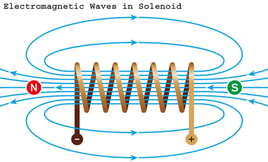
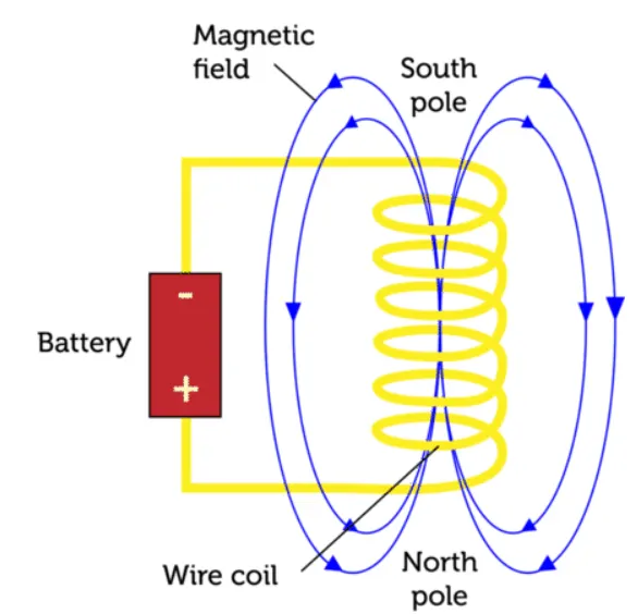
A solenoid is a type of electromagnet, the purpose of which is to generate a controlled magnetic field through a coil wound into a tightly packed helix. The coil can be arranged to produce a uniform magnetic field in a volume of space when an electric current is passed through it. The term solenoid was coined in 1823 by Andre-Marie Ampere to designate a helical coil.
Simulink Model:
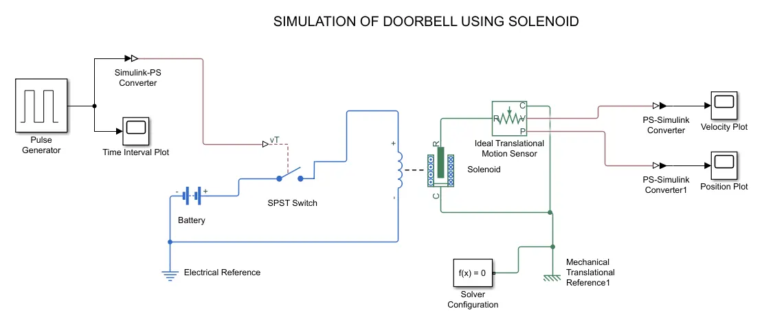
Blocks Used:
Pulse Generator: To generate time signals to control the switch operation.
Simulink-PS Converter: The Simulink-PS Converter block converts the input Simulink signal into a physical signal.
Scope: The Scope is optimized for general time-domain simulation.
Battery: Power source for the bell to ring.
SPST Switch: An ON/OFF control switch (Single-pole single-throw Switch)
Electrical Reference: Electrical conserving ports of all the blocks that are directly connected to ground.
Solenoid: To generate magnetic field to attract the hammer to ring the bell.
Ideal Translational Motion Sensor: The Ideal Translational Motion Sensor block represents a device that converts an across variable measured between two mechanical translational nodes into a control signal proportional to velocity or position.
Mechanical Translational Reference: All translational ports that are rigidly clamped to the frame (ground).
PS-Simulink Converter: The Simulink-PS Converter block converts the physical signal into a input Simulink signal.
Flow Process:
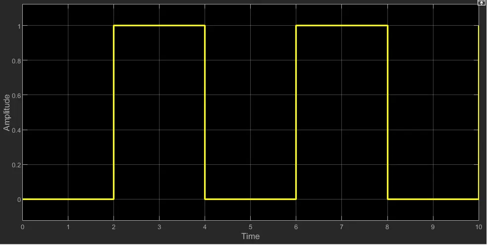
- First generate the signals in Pulse generator for every 2 sec to control the switch to ring the bell.
- The generated signals are plotted using scope and then convert simulink signals into the real time physical signals using Simulink-PS converter.
- Then according to the signals, the SPST switch acts to control the flow of the current to the solenoid with the help of battery (12V).
- When the current is passed to the solenoid it generates magnetic field to attract the iron armature.
- From the solenoid the motion is sensed using Ideal Translational Motion sensor.
- Then the signals are converted to simulink signals by the help of PS-Simulink converter to record the motion of hammer.
Results:
Generated Time Plot:
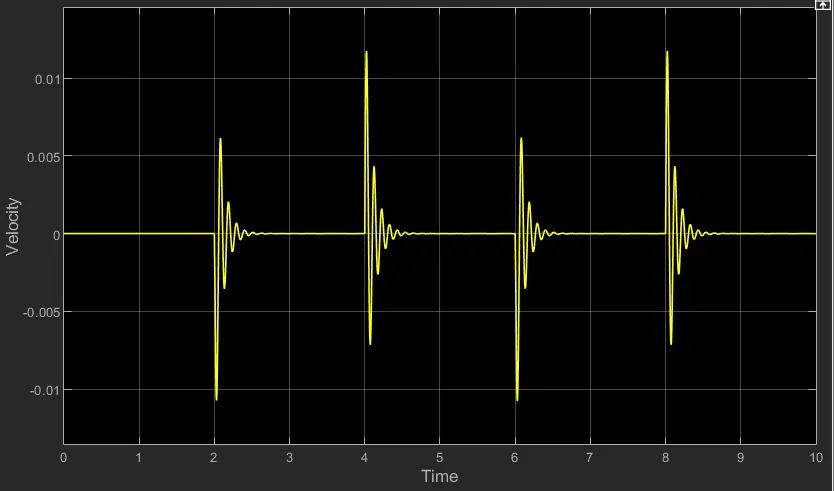
Velocity Plot(Plunger):
Position Plot(Plunger):
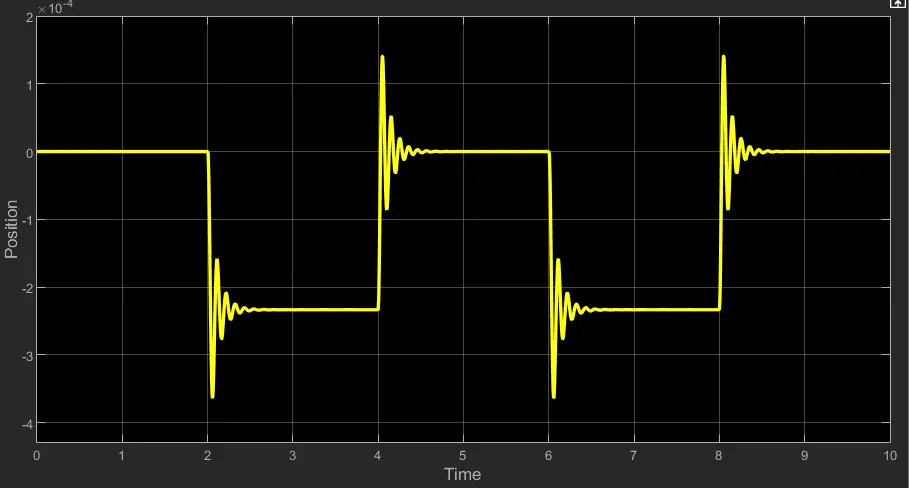
Conclusion: Simulating the doorbell using solenoid and generate signals to creat a situation where the switch is closed for 2 seconds and then released, then recorded the physical movement(Velocity & Position)of the plunger.
SIMULINK MODEL OF A THERMISTOR TO SENSE THE TEMPERATURE OF A HEATER TO CONTROL THE FAN
Theory:
Thermistor:
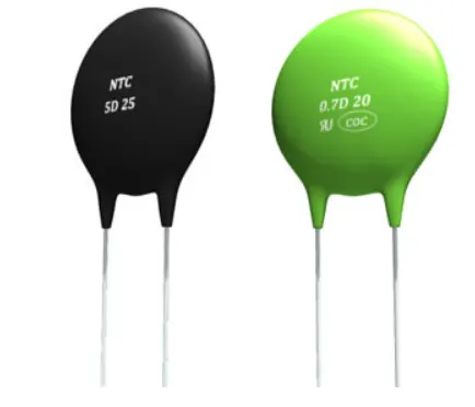
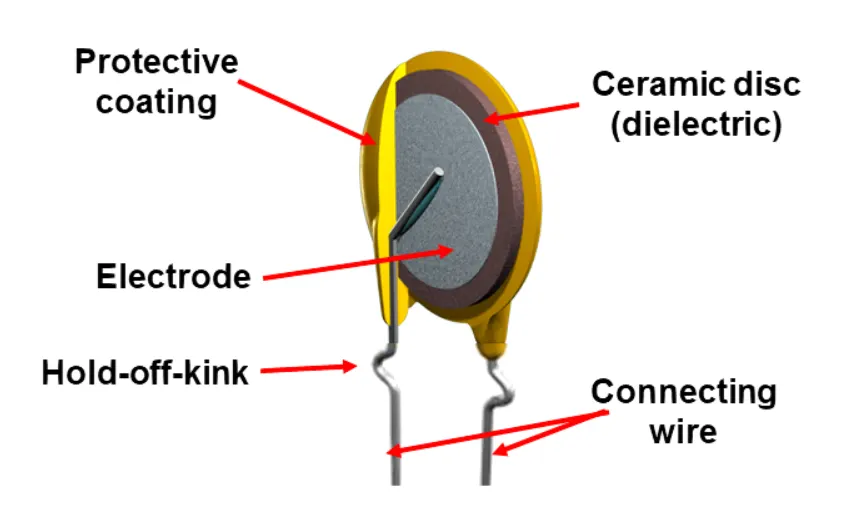
A thermistor is a type of resistor whose resistance is dependent on temperature, more so than in standard resistors. The word is a combination of thermal and resistor. Thermistors are widely used as inrush current limiters, temperature sensors (negative temperature coefficient or NTC type typically), self-restting overcurrent protectors, and self-regulating heating elements (positive temperature coefficient or PTC type typically).
Thermistors are of two opposite fundamental types:
- With NTC thermistors, resistance decreases as temperature rises. An NTC is commonly used as a temperature sensor, or in series with a circuit as an inrush current limiter.
- With PTC thermistors, resistance increases as temperature rises. PTC thermistors are commonly installed in series with a circuit, and used to protect against overcurrent conditions, as resettable fuses.
Simulink Model:
Blocks Used:
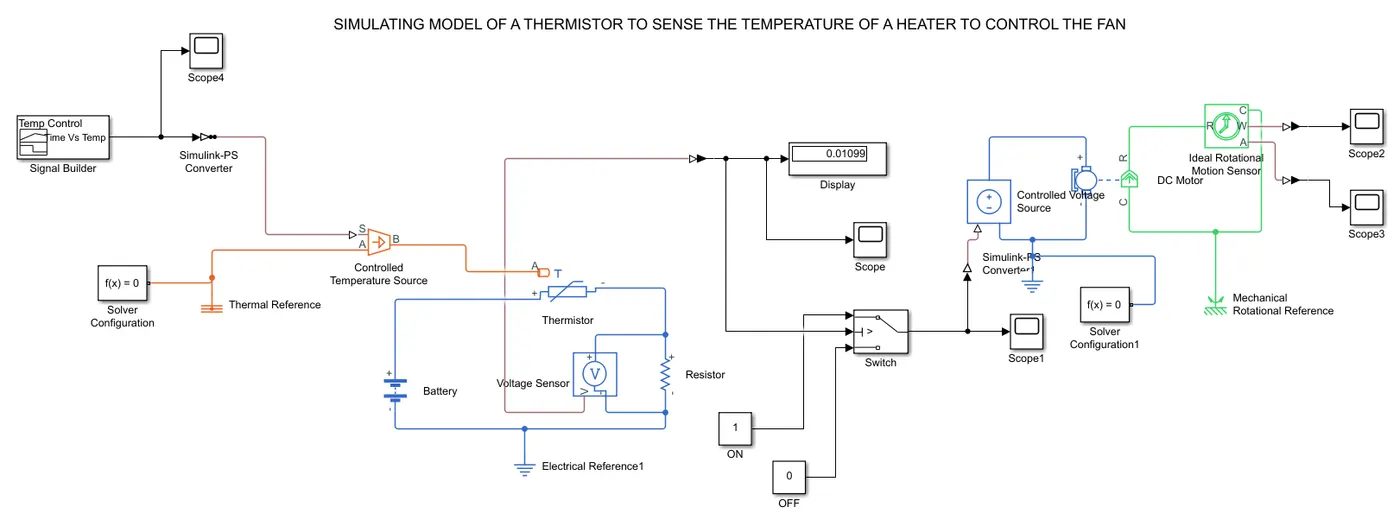
Signal Builder: For inputting temperature at different time intervals.
Scope: The Scope is optimized for general time-domain simulation.
Simulink-PS Converter: The Simulink-PS Converter block converts the input Simulink signal into a physical signal.
Thermistor: To sense the temperature for producing resistance.
Battery: Power source for thermistor.
Electrical Reference: Electrical conserving ports of all the blocks that are directly connected to ground.
PS-Simulink Converter: The Simulink-PS Converter block converts the physical signal into a input Simulink signal.
Voltage Sensor: To sense the voltage across the circuit.
Display: To view the threshold value of the voltage.
Switch(Threshold Controlled): To control the voltage output at particular threshold value.
DC Motor: To run at controlled voltage.
Ideal Rotational Motion Sensor: To sense the working of DC Motor.
Mechanical Translational Reference: All translational ports that are rigidly clamped to the frame (ground).
Flow Process:
- By using signal builder generate the time interval with various temperature as a source of heater.
Temperature source: 20 °C from 0 to 10 seconds, 27 °C from 10 to 30 seconds, 23 °C from 30 to 50 seconds
Fan conditions: ON if the temperature above 25 °C, OFF otherwise
- Next the temperature data is passed to thermistor to sense and generate the resistance value accordingly.
- As the resistance(R) varies accordingly to the current(I), Voltage across it being sensed using voltage sensor.
- That voltage is inputed to (Threshold Controlled) switch for turning ON the motor(Fan) with a threshold value of '0.01099'.
- Then for the particular value T=27°C controlled voltage supplies the respective voltage to run the DC motor.
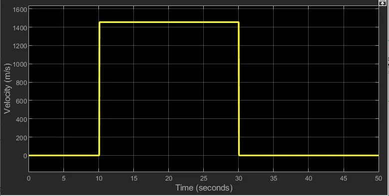
- Using the ideal Rotational Motion Sensor the outputs from DC Motor are plotted in the Velocity and Angular displacement scopes.
Signals Generated from Signal Buider
Results:
Time Vs Voltage:
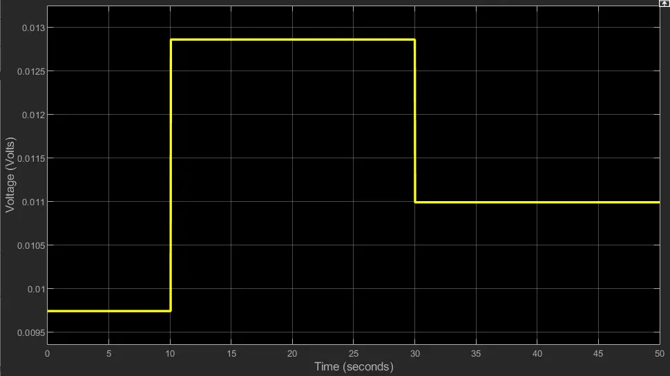
From this plot we can conclude that the voltage is generated according to the temperature input w.r.t time. So the maximum voltage at T=27°C is 0.01286V
Time Vs Controlled voltage:
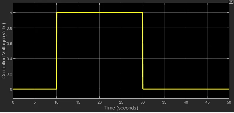
From this lot we can understand that the voltage is obtained for (10-30s) at T=27°C to turn on the DC Motor, the threshold value used is '0.01099'
Time Vs Velocity:
Time Vs Angular displacement:
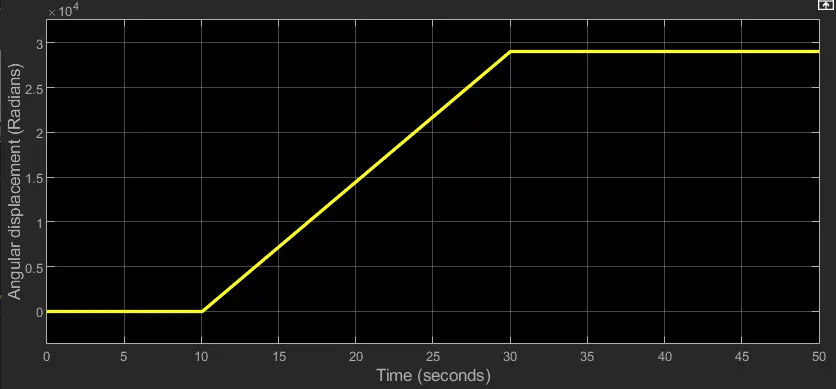
Conclusion: Simulating the above model and created the conditions for temperature source: 20 °C from 0 to 10 seconds, 27 °C from 10 to 30 seconds, 23 °C from 30 to 50 seconds and then recorded the Velocity and Angluar displacement of the fan as per fan conditions: ON if the temperature above 25 °C, OFF otherwise.
References:
https://in.mathworks.com/help/simulink/
https://in.mathworks.com/help/physmod/sps/examples/thermistor-controlled-fan.html?s_tid=srchtitle