Week -2
Title :
- To make a simulink model of a Doorbell uasing solid blocks.
- To use a thermistor and sense the themperature of the heater and simulating fan by turning it ON/OFF.
Doorbell Simulink Circuit :
Circuit Explanatoin :
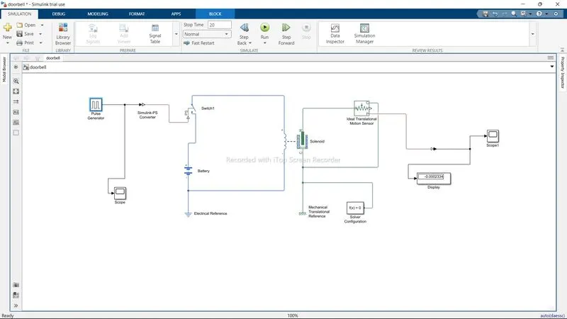
- A PULSE GENERATOR is used to generate the frequency as an some input. The inputs given are.
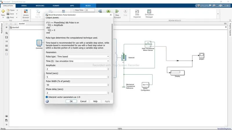
- A Simulink_PS converter is used to conver the input signal from pulse generator.
- The Switch Block is used as an external physical signal. If the external signal is greter then the switch is closed or else open.
- BATTERY is connected to the circuit whose +ve terminal is to the switch end and its -ve terminal is to the ELECTRICAL REFERENCE as shown.
- The Battery connections are connected to the SOLENOID whos eends are connected.
- IDEAL TRANSLATION MOTION SENSOR is used whose name suggest it is an ideal sensor which only measures velocity and displacement in a mechanical translation network.
- This sensor has two outputs which is connected to solenoid and other to the PS-Simulink converter.
- A Solver configuration is added for the sinulation uing inbuilt function.
- The DISPLAY BLOCK gives out the output of the curcuit after running.
- The SCOPE shows the Output graph of the circut.
- The Scope to the left shows.
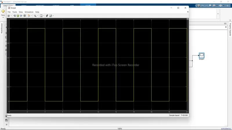
- The Graph shows pulse at every 2 sec interval.
- The graph by SCOPE 1 to the right shows.
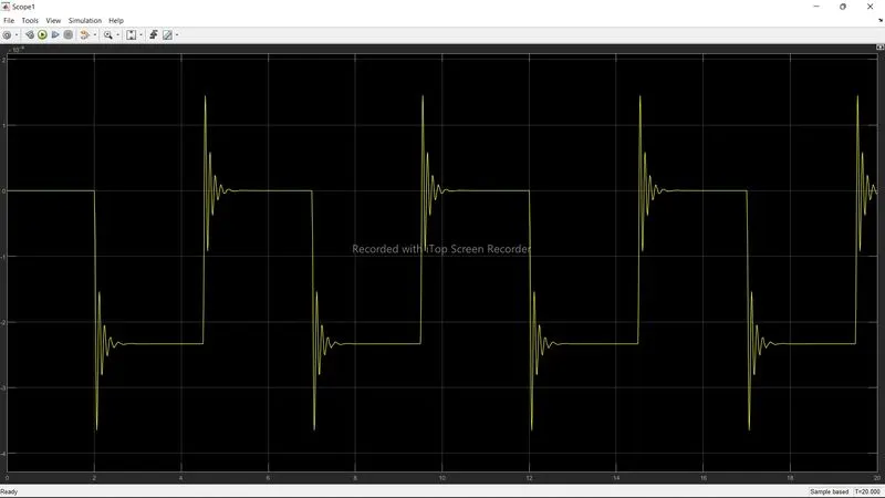
- The doorbell groph shows the amplitude and the damping of vibration in regular interval of time.
THERMISTOR.
- THe citcuit digram for the thermistor is shown as
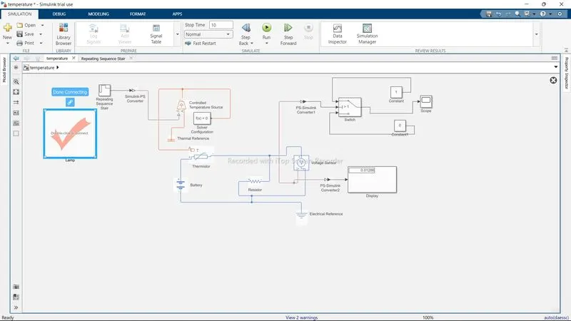
- Citcuit comprises of LAMP to turn on or off as the temperature of the thermistor fluctuates.
- REPEATING SEQUENCE STAIR is used to the input parameters which is. 293K for 10 sec,300K and 297K for 20 seconds each.
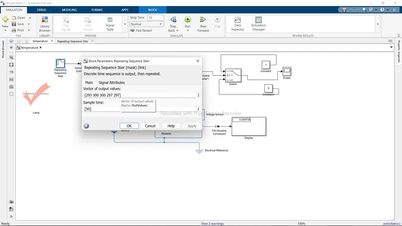
- A SIMULINK-PS converter is used to convert the input signal to physical signal.
- A CONTROLLED TEMPERATURE SOURCE block is used which is a source of ideal energy in thermal network independent of the heat input. It alwas maintainsthe temperature.
- This is conneced to TEMPERATURE REFERENCE which helps to maintain temp.
- A SOLVER CONFIGURATION is used to resolve input with the inbuilt function.
- The solver and controlled temp. source is connected to the THERMISTOR.
- Thermistor is a high resistance device whose resistance is dependent on the temperature.
- This is connected the BATTERY for the power supply and further connected to electrical reference.
- A RESISTOR is conneced to VOLTAGE SENSOR which converts the voltage into the physical signal and display on the output DISPLAY screen with the help of PS-simulink converter.
- This voltage sensor is connected to the switch with other ps simulink converter.
- The CONSTANTS blocksare added adn value is given fot the swith terminals.
- The LAMP turn RED (OFF) when the temperature is below 298K or else it turn GREEN (ON).