Week -2
Aim: 1) To make a Simulink model of doorbell using solenoid.
2) To make a model using thermistor to sense the temperature of a heater & turn on or turn off the fan.
Objective: 1) To create a model of doorbell using solenoid & create a situation where the switch is closed for 2 sec and then released and observe the physical movement of the plunger.
2) To use thermistor to sense the temperature of a heater & turn on or off the fan as per the conditions given below:
- Temperature source: 20℃ from 0 to 10 sec, 27℃ from 10 to 30 sec, 23℃ from 30 to 50 sec
- Fan condition: ON if the temperature is above 25℃, OFF otherwise
Answer 1:
The model of doorbell using solenoid block is shown below in Figure 1.
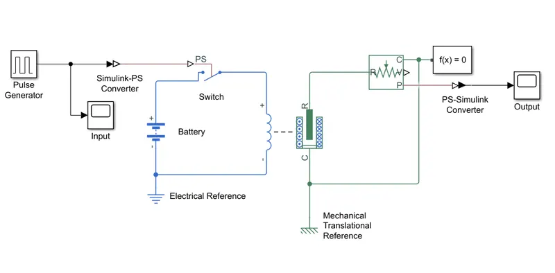
Figure 1
- As shown in Figure 1, solenoid coil is connected with a battery through a SPST switch.
- The switch is required to be closed for 2 sec. This ON/OFF operation of switch is controlled by a pulse generator.
- Plunger part of the solenoid block is connected with an ideal translation motion sensor which detects the position change of the plunger.
- A scope is connected with pulse generator and ideal translation motion sensor to see their output.
The results of the scope are shown below in Figure 2.
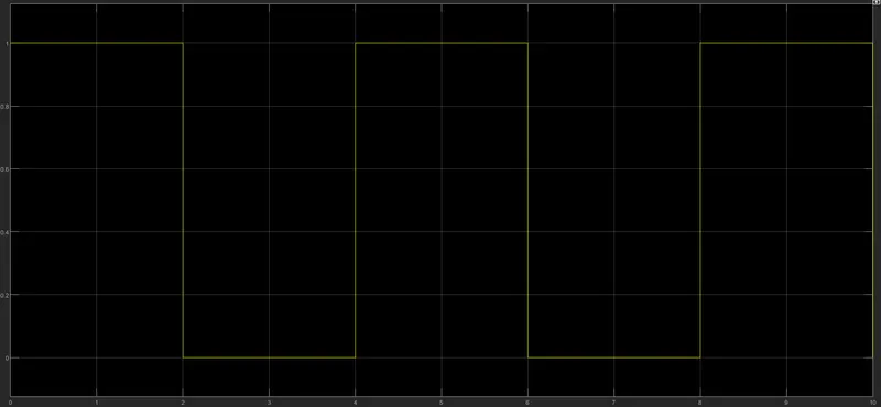
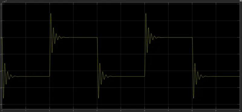
Figure 2
- Upper graph shows the switching operation of the switch with the help of pulse generator.
- The switch is OFF at t = 0 & 1 sec and is ON at t = 3 & 4 sec i.e., for 2 sec as required.
- Lower graph shows the output of ideal translation motion sensor.
- As shown, when switch is OFF, the position of the plunger is at 0 which can be considered as the initial condition of the plunger.
- Now when switch is closed the plunger gets attracted towards the electromagnet. This can be seen in the graph with the position of the plunger at -5.
- After 2 sec, when switch is OFF again, the plunger is no longer attracted towards the electromagnet and is released to its original position i.e., at 0 in graph.
Answer 2:
It is required to make a model using a thermistor where the temperature of a heater goes above 25℃, the fan turns ON.
But first, it is necessary to understand the function of a thermistor. The thermistor is a type of resistor whose resistance is depended on the temperature. There are two types of thermistors: (i) NTC, (ii) PTC.
- NTC (Negative Temperature Coefficient): With increase in temperature, the resistance of these type of thermistors decreases.
- PTC (Positive Temperature Coefficient): With increase in temperature, the resistance of these type of thermistors increases.
In this model, a PTC type thermistor is used.
A simple thermistor circuit is shown below in Figure 3.
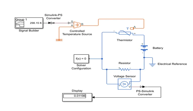
Figure 3
- To create an effect of a heater, a controlled temperature source block is used.
- It is connected a signal builder block which generates the signals according to the requirements.
- This controlled temperature source block is also connected with a thermistor block which will sense the change in temperature and accordingly change its resistance.
- A battery and a resistor are also connected in series with the thermistor. The addition of the voltage drops between thermistor and resistor is the voltage of the battery. As there is a change in the temperature, there will be a change in the resistance of the thermistor. This will also result in the change of the voltage drop across the thermistor and the resistor. A voltage sensor is connected across the resistor to detect the change in its voltage drop.
Now, given threshold temperature after which the fan needs to be turned ON is 25℃ (298.15 K).
So, we need to know the voltage drop across the resistor at 25℃. Figure 3 is the model to know the same. From the display connected to the voltage sensor, it can be seen that the voltage drop across resistor is 0.01196 V for the threshold temperature of 25℃.
We can now start modelling the asked system which is shown in Figure 4.
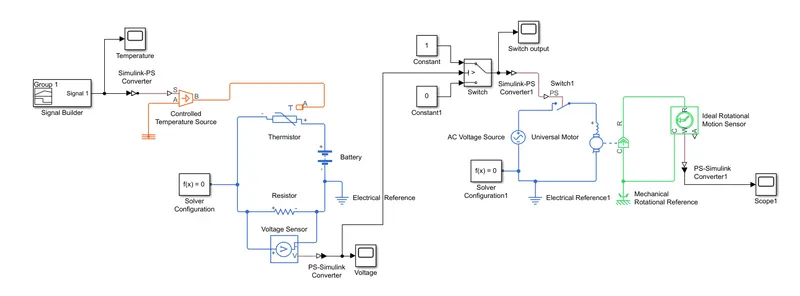
Figure 4
As asked, the temperature of the heater should be 20℃ (293.15 K) from 0 to 10 sec, 27℃ (300.15 K) from 10 to 30 sec & 23℃ (296.15 K) from 30 to 50 sec. So, with the help of signal builder, a signal is created which can be given to the controlled temperature source to generate asked temperature variations. The output of signal builder is shown in Figure 5 below.
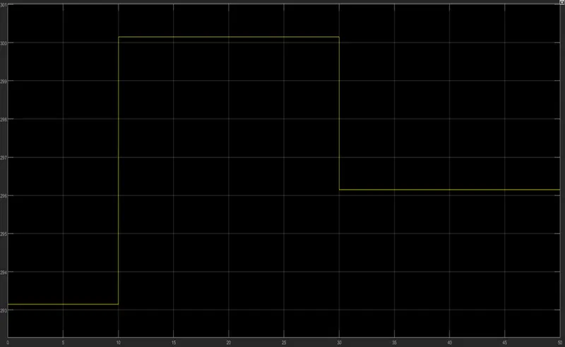
Figure 5
As a fan, a universal motor block is used which is connected with a single phase 50 Hz, 230 V AC supply through an SPST switch. The switching operation is depended on the output of the voltage sensor. If voltage sensor output is less than the threshold value which is 0.01196 V then the switch is open and when the voltage sensor output is greater than the threshold value then the switch is closed and the fan gets turned ON.
The output of voltage sensor for different temperatures is shown below in Figure 6.
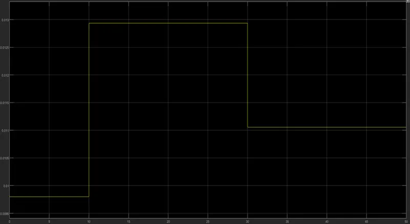
Figure 6
The switching operation is controlled by a SPDT switch. The output of the voltage sensor block is given to this switch. If the output of voltage sensor is greater than 0.01196 V then SPDT switch selects constant block with value 1 which signals the SPST switch to be closed and if the output of voltage sensor is less than 0.01196 V then SPDT switch selects constant block with value 0 which signals the SPST switch to be open.
The switching operation in the form of graph is shown below in Figure 7.
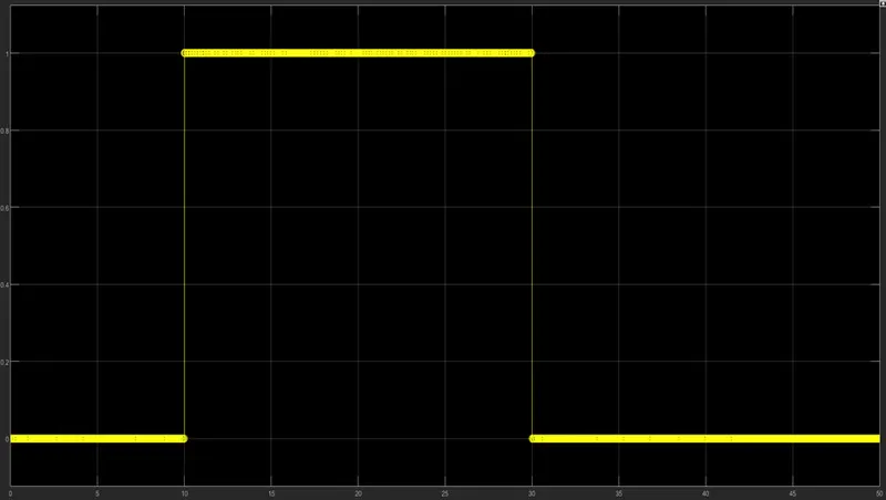
Figure 7
- From the Figure 7, it can be seen that when the switch is closed between 10 to 30 sec. The temperature between this period is 27℃ which is greater than 25℃.
- An ideal rotational motion sensor is connected with the rotor of universal motor block. This sensor detects the angular velocity of the rotor.
The output of the ideal rotational motion sensor is shown below in Figure 8.
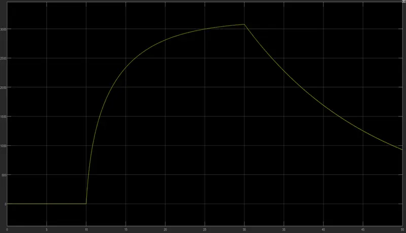
Figure 8
- From the Figure 8, it can be seen that the motor starts rotating at t = 10 sec and accelerates upto t = 30 sec. Then motor starts to deaccelerate.
Conclusion:
- From the solenoid based doorbell model, we see that the plunger is attracted towards the solenoid when the switch is closed and in turn ring the bell.
- From the thermistor based model, we can say that the thermistor is a transducer which senses the change in temperature which is a physical quantity and converts it into an electrical quantity by changing its resistance accordingly.