Week -2
1) Simulink model of Doorbell using solenoid block :
What is solenoid?
- A solenoid is a device comprised of a coil of wire, the housing and a moveable plunger (armature).
- When an electrical current is introduced, a magnetic field forms around the coil which draws the plunger in.
- More simply, a solenoid converts electrical energy into mechanical work.
What is the function of solenoid?
- A solenoid works by producing an electromagnetic field around a movable core, called an armature.
- When compelled to move by the electromagnetic field, the motion of that armature opens and closes valves or switches and turns electrical energy into mechanical motion and force.
Elements used in simulink model of Doorbell :
The following elements (or) blocks were used in the construction of simulink model of doorbell using solenoid block.
Simulink elements :
- Pulse generator
- Scope
- Solver configuration
Simscape Utility elements :
- PS - Simulink converter
- Simulink - PS converter
Simscape Electrical elements :
- Battery
- Simscape Switch
- Electrical reference
Simscape Mechanical elements :
- Solenoid
- Ideal transitional motion sensor
- Mechanical Transitional reference
Construction :
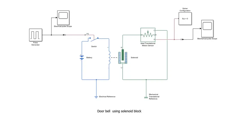
- Initially the input electrical source (battery) is added.
- To regulate (or) control the supply a simscape switch is added and connected with positive terminal of the battery.
- Solenoid block is added and connected with the negative terminal of switch and the circuit is clossed by connecteing the negative terminal of the solenoid coil with the battery negative eterminal.
- To avoid leakage an electrical reference is connected in between the solenoid coil and battery.
- The Plunger of the solenoid is connected to the Ideal Transitional motion sensor to monitor the motion of plunger.
- The sensor will have three output ports to calculate the velocity (v port) , Reference (c port) and Position (p port).
- The reference port of the solenoid is connected with the referene port of the solenoid to complete the circuit.
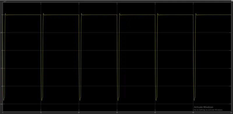
- To calculate the pulse from the sensor a scope is added with the position port of the sensor. We can not directly connect the sensor with the scope because scope is a simulink block and sensor is a simscape block , hence a PS - simulink converter is used to connect.
- Also a solver configuration is used as a simple function between the sensor and scope.
- Now, to regulate the pulse from the input a pulse generator is used and is connected with the help of Simulink - PS converter to the ps port of the switch.
- A scope is added to regulate the generated pulse from the generator to the switch.
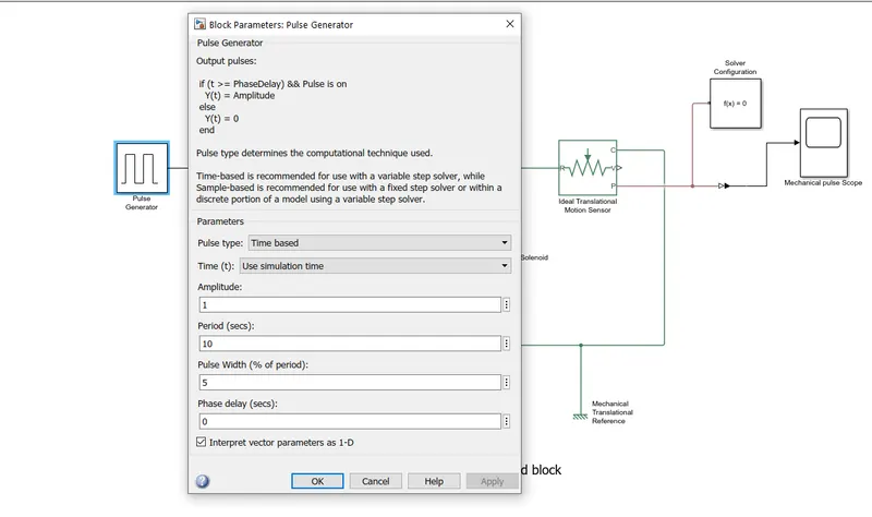
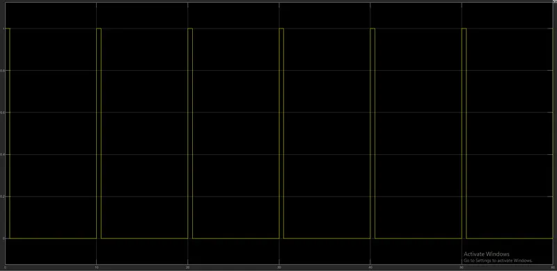
- By double clicking the pulse generator we can varry the input time period, and is shown below.
- After regulating the time period both the plots are verified for the equal amplituted.
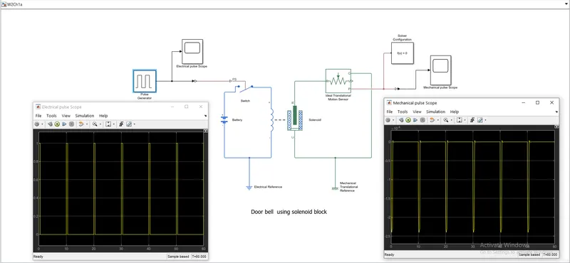
- Plot at the pulse generator scope.
- Plot at the snensor scope.
2)Use a thermistor to sense the temperature of a heater & turn on or turn off the fan
What is thermistor and its principle?
A thermistor (or thermal resistor) is defined as a type of resistor whose electrical resistance varies with changes in temperature. Although all resistors' resistance will fluctuate slightly with temperature, a thermistor is particularly sensitive to temperature changes.
Simulink Elements :
- Repeating sequence stair
- SOlver configuration
- Constants
- Switch
- Display
- Scope
Simscape Utility elements :
- PS - Simulink converter
- Simulink - PS converter
Thermal elements :
- Controlled temperature source
- Thermal reference
Electrical elements :
- Thermistor
- Battery source
- Resistor
- Voltage sensor
- Electrical reference
Construction :
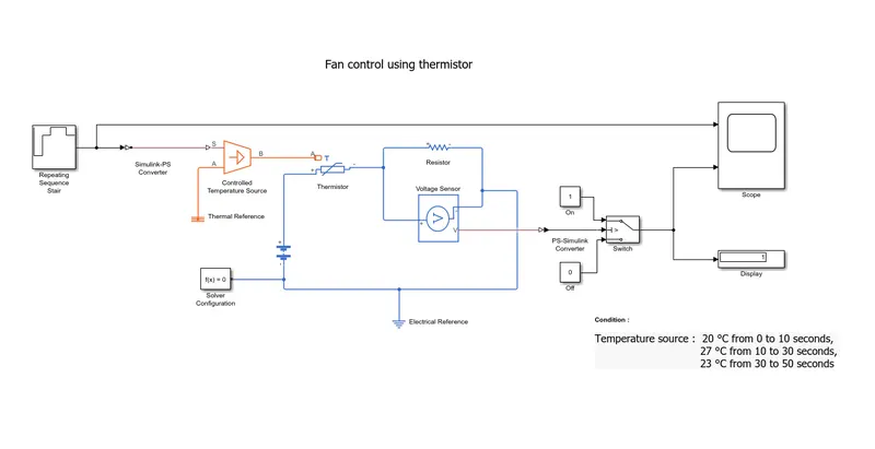
- The required elements are taken from the library.
- Initially a battery is connected with the thermistor.
- The thermistor is connected with the resistor and voltage sensor in series.
- Then the circuit is closed by connecting with the negative terminal of the battery.
- The Controlled temperature sensor's (CTS) B-port is connected with the A-port of the thermistor.
- The S-port of the CTS is connected with the input constant block initially to find the threshold value for the switch at 298 K.
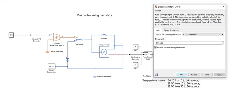
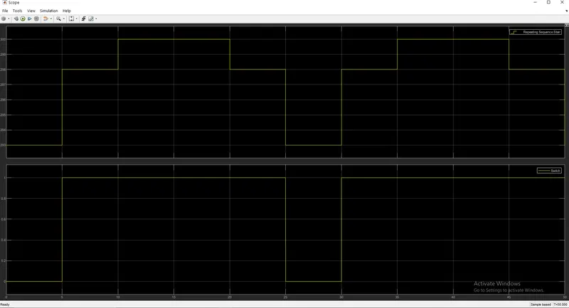
- After find the threshold value the constant can be removed instead a Repeating Sequence stair can be added with the CTS.
- The time limits are divided into 5 intervals with a gap of 10secs and the temperature values are given as input in the Repeating sequence stair with sample time as 5 secs.
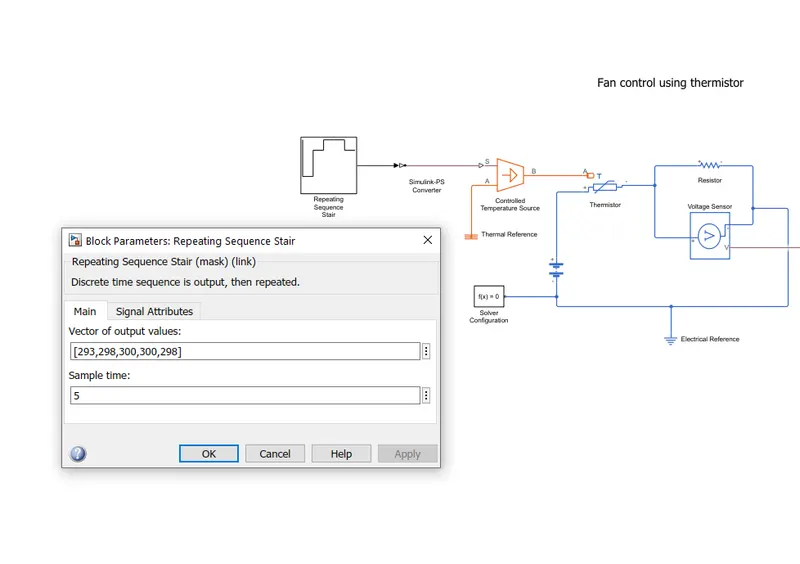
- Simulink block representaion for the fan control using thermistor.
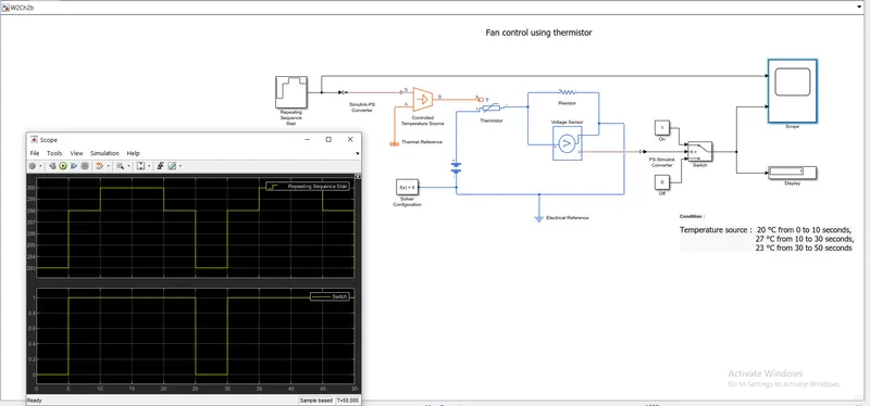
- Plot for the thermistor controlled fan for a time period of 50 secs , and the time sample taken as 5 secs for the stair.