Week -2
- Make a Simulink model of Doorbell using solenoid block with the following details:
In the above arrangement, when the switch is closed the electromagnet receives electrical power from the battery and pulls the metal arm to hit the bell producing sound.
Create a situation where the switch is closed for 2 seconds and then released. Observe the physical movement of the plunger.
SIMULINK MODEL
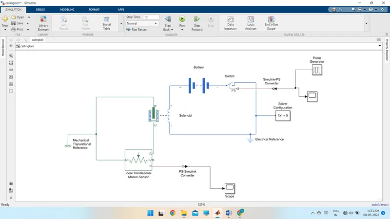
- Calling bell consists of both electrical and mechanical elements.
- Battery block is used in the circuit as an input voltage source.
- Switch is used to control the on and off voltage in the circuit.
- Pulse generator is used to give input signal to the switch to close the circuit.
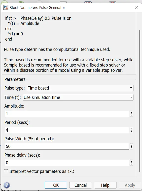
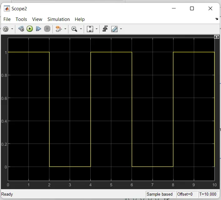
To give input signal for two seconds to the switch.
- Signal is given for total time period of 4 seconds.
- In total time period 50 % of signal is used to switch on the circuit (i.e. for 2 sec) and the other two seconds is used to switch off the circuit.
- Input signal is observed by connecting scope to the input pulse generator.
- Simulink-Ps connecter is used to connect pulse generator to convert input signal to physical signal.
- Solenoid is used to convert electrical energy to mechanical energy.
- Ideal Translational Motion Sensor is used to sense the movement caused by solenoid due to input signal.
- PS-Simulink Converter is used to convert physical signal to Simulink output signal.
- Mechanical Translational Reference is added to the circuit as mechanical blocks present in the circuit.
- Electrical Reference is added to the circuit as electrical blocks present in the circuit.
Result:
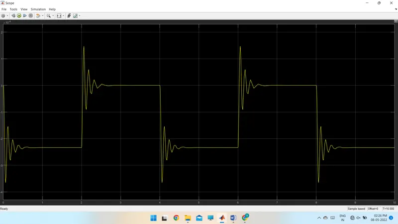
In Ideal Translational Motion Sensor physical signal port ‘P’ is connected to scope with the help of PS-Simulink Converter as to observe the physical movement of the plunger.
The movement of plunger is shown in the following plot
Use a thermistor to sense the temperature of a heater & turn on or turn off the fan as per the below conditions:
Temperature source: 20 °C from 0 to 10 seconds, 27 °C from 10 to 30 seconds, 23 °C from 30 to 50 seconds
Fan conditions: ON if the temperature above 25 °C, OFF otherwise
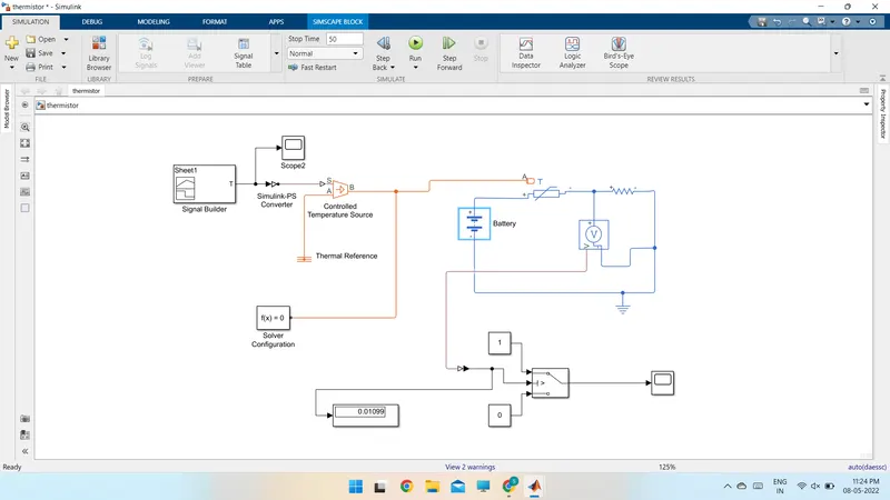
- To model this simulation, the input given temperature data is tabulated in excel file.
- Using signal builder input signal is created by importing saved excel data file.
- Scope is attached to signal builder to verify output of signal builder.
- Output of signal builder is given as input to controlled temperature source.
- Controlled temperature source is connected to thermistor thermal port.
- A resistor is connected in series to the thermistor and a voltage input is connected to the loop.
- A voltage sensor is connected parallel to the resistor to sense the voltage drop in the resistor.
- Output of minimum voltage drop is given as threshold value of the switch.
- Output of switch is connected to scope.
- Total simulation runtime is 50
Simulink model
Input signal in signal builder
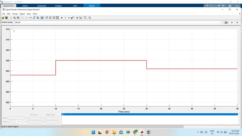
Input temperature values is converted to kelvin from degree centigrade.
Results
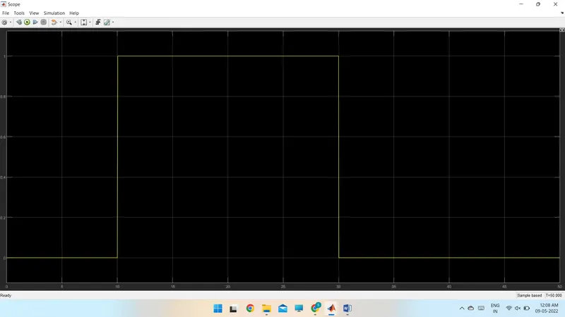
As we required the output signal is 1 (i.e. on condition) when the temperature is more than 25C (i.e. from 10 to 30 seconds Where the value is 27C).