Week -2
Question:
- Make a Simulink model of Doorbell using solenoid block with the following details:
-
Use a thermistor to sense the temperature of a heater & turn on or turn off the fan as per the below conditions:
Aim:
-This challenge aims to modeling and simulating a door bell with the use of a solenoid block. The Door bell should ring for 2 seconds when the switch is closed and then stops
-The second simulatin aims to model and simulate the a heater using a theristor. The theristor sense the temperature of a heater and turn on or turn off the fan as per the below conditions.
-Temperature source: 20 °C from 0 to 10 seconds, 27 °C from 10 to 30 seconds, 23 °C from 30 to 50 seconds
Fan conditions: ON if the temperature above 25 °C, OFF otherwise
1) What is DoorBell:
A doorbell is a signaling device typically placed near a door to a building's entrance. When a visitor presses a button the bell rings inside the building, alerting the occupant to the presence of the visitor. Although the first doorbells were mechanical, activated by pulling a cord connected to a bell, modern doorbells are electric, operated by a pushbutton switch.Pressing the doorbell pushbutton switch momentarily closes the doorbell circuit. One terminal of this button is wired to a terminal on a transfrmer. A doorbell transformer steps down the 120 or 240-volt AC electrical power to a lower voltage, typically 10 to 24 volts. The transformer's other terminal connects to one of three terminals on the signaling device. Another terminal is connected to a wire that travels to the other terminal on the button. Some signaling devices have a third terminal, which produces a different sound
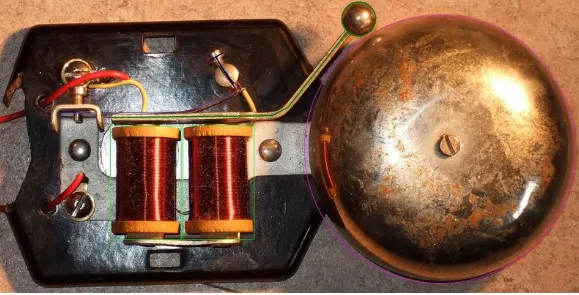
What is a solenoid:
A solenoid is a device comprised of a coil of wire, the housing and a moveable plunger (armature). When an electrical current is introduced, a magnetic field forms around the coil which draws the plunger in. More simply, a solenoid converts electrical energy into mechanical work.
Model:
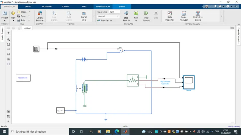
*For this simulation a puls generator is connected to a switch to give switch on and off puls.
-The switch is connected to a battery and a solenoid in a closed loop circuit as shown above.Hence the switch serves as closing and openning the circuit.
-The solenoid is then connected to a Ideal Translational Motion Sensor to simulate
the vibration of the bell.
-A mechanical Translational reference and an Electrical Reference is used to connect the ground.
-A scope is then used to observe the simulation.
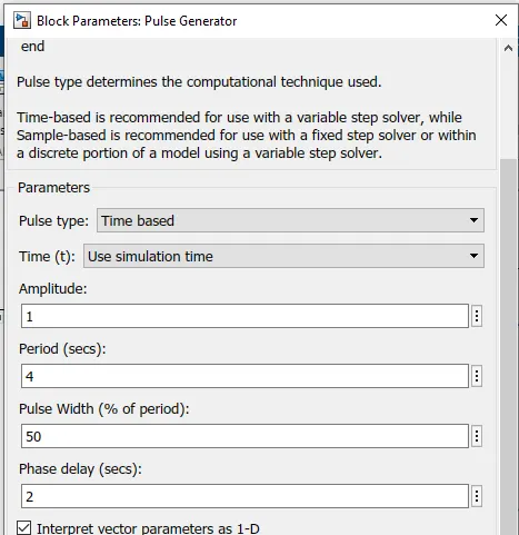
*The pulse generator is configured as shwon below.
Results:
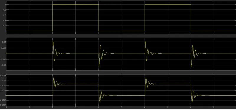
From the above simulation we observe the following.
-The first plot is that of the puls generator which gives the switching on and off of the switch. The switch is switched on and off every 2 seconds.
-The second plot is the measured velocity measured on the R port of the Ideal Translational Motion Sensor when voltage is given in by the solenoid.
-The third plot is the position of the vibrating bell. we see that vibration is observed when the puls is at an amplitude of 1.
2) What is a Theristor:
A thermistor is a resistance thermometer, or a resistor whose resistance is dependent on temperature. The term is a combination of “thermal” and “resistor”. It is made of metallic oxides, pressed into a bead, disk, or cylindrical shape and then encapsulated with an impermeable material such as epoxy or glass.Thermistors, derived from the term thermaIly sensitive resistors, are a very accurate and cost- effective sensor for measuring temperature. Available in 2 types, NTC (negative temperature coefficient) and PTC (positive temperature coefficient), it is the NTC thermistor that is commonly used to measure temperature.
Simulation:
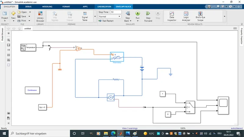
*The model was builed as shown above. A signal builder is used to simulate the the tempirature change relative to time, then given to a theristor which is in a closed current circuit. A voltage sensor is used to detect the change in voltage during tempirature rise and fall and thereby switching on and off the fan when appropriat.
Signal Builder:

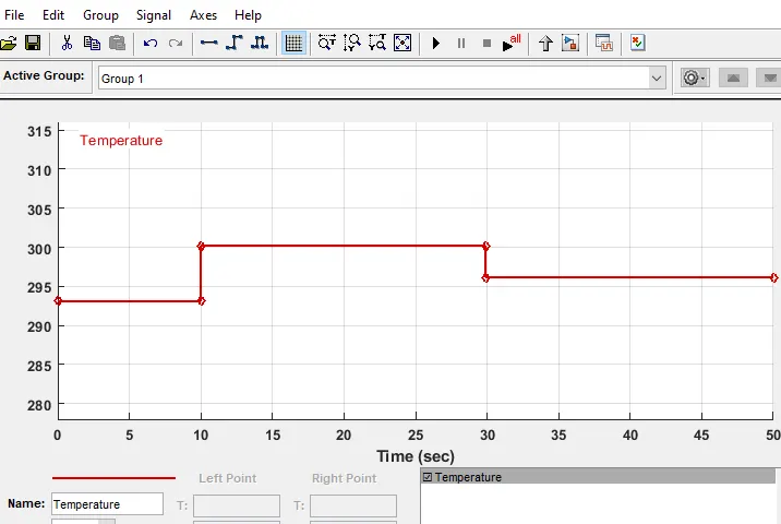
With the signal builder the temperature in reference to time is simulated and given to the Thermistor. The temperature is given in kelvin (1°c = 293.15K) Hence adding a value of 293.15 to all celcius value.
Controlled Temperature Source:
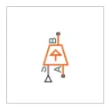
The Controlled Temperature Source block represents an ideal source of thermal energy that is powerful enough to maintain specified temperature difference across the source regardless of the heat flow consumed by the system.Connections A and B are thermal conserving ports corresponding to the source inlet and outlet, respectively. Port S is a physical signal port, through which the control signal that drives the source is applied. You can use the entire variety of Simulink signal sources to generate the desired heat flow variation profile. The temperature differential across the source is directly proportional to the signal at the control port S.
Thermistor:
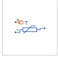
The Thermistor block represents an NTC thermistor using the B-parameter equation. The resistance at temperature T. The Temperature change in respect to time from signal builder block is given in Port A and terminal (+Ve) and (-Ve) is connected to voltage sensor and voltage source.
Voltage Sensor:
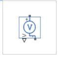
The Voltage Sensor block represents an ideal voltage sensor, that is, a device that converts voltage measured between two points of an electrical circuit into a physical signal proportional to the voltage. Connections + and – are electrical conserving ports through which the sensor is connected to the circuit. Connection V is a physical signal port that outputs the measurement result.
Voltage Source:
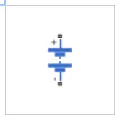
The Battery block represents a simple battery model. The block has four modeling variants, accessible by right-clicking the block in your block diagram and then selecting the appropriate option from the context menu,
Results:
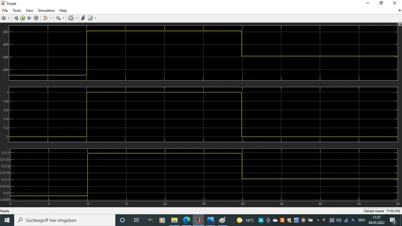
*From the above simulation results we could see three plots. The first is just the plot of the signal builder which plots the temperature variation with resect to time.
The third plot is that of the voltage sensor showing the rise and fall of voltage across the circuit due to rise and fall of temperature.
The second plot shows the fan switching on and off(0 represents off while 1 represents 0n). We notice that from 0 to 10 sec the fan is switched of at 0 because the temperature is below 25°c and just above 10sec when the temperature is above 25°c the fan is switched on. above 30sec the fan switches off cause the temperature is below 25°c.