Week -2
REPORT
Simulink model of Doorbell
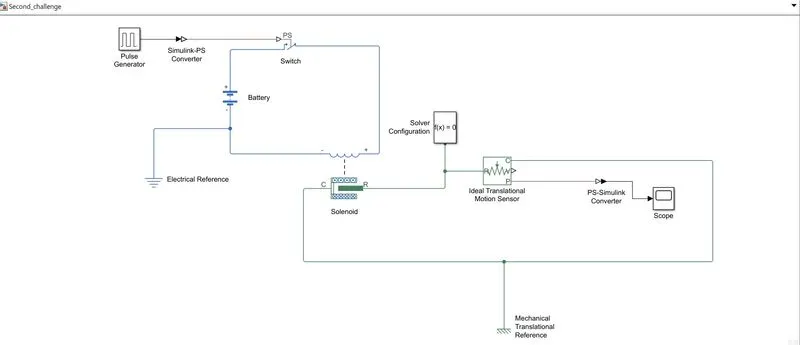
The above shown is a Simulink model of a Doorbell.
- First a Pulse Generator is used to Generate square wave pulses at regular intervals.
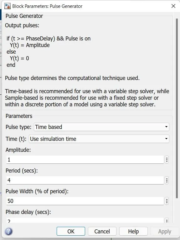
- A pulse is generated with 1 amplitude for a period of 2 sec with a phase delay of 2 sec.
- In phisical terms the switch will be pressed for 2 sec.
- Using a Simulink-PS Converter the simulink pulse is converted to Physical Signal.
- This physical signal is given to switch.
- A Solenoid is connected to the circuit which is controlled by the Switch and powered by a Battery.
- Thus when the circiut is closed a electro magnetic current forces the spring to produce a mechanical movement.
- This mechanical movement is utalized to ring the bell.
- It is observed using a Ideal Translational Motion Sensor.
- The out put is studied using a Scope.
RESULT
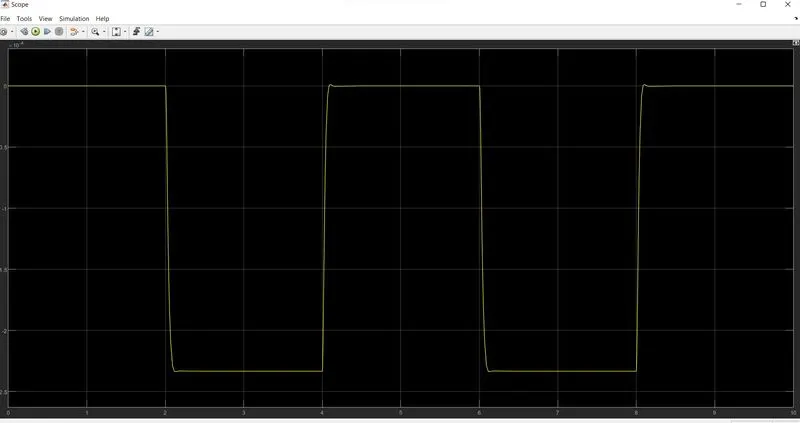
From the above graph it is cleared that at 1st 2 sec when the switch is open no deflections are observed then next 2 sec when the switch is closed a deflection is observed. This pattern continues for 10 sec.
Thermistor to Sense the Temperature of a Heater
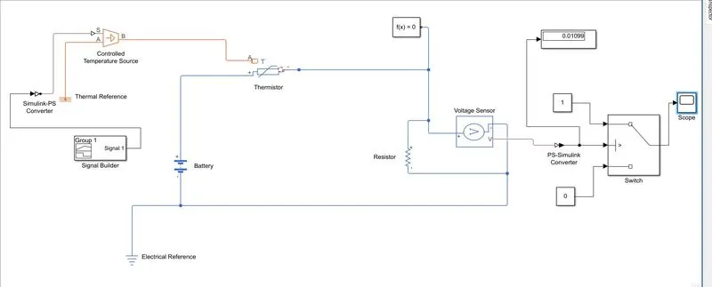
The above shown is a simulink model of a Thermistor to sense the temperature of a heater & turn on or turn off the fan as per the below conditions:
Temperature source: 20 °C from 0 to 10 seconds, 27 °C from 10 to 30 seconds, 23 °C from 30 to 50 seconds
Fan conditions: ON if the temperature above 25 °C, OFF otherwise.
- First we use a Signal Builder to produce the signals according to input conditions.
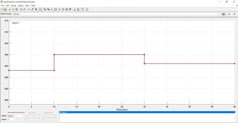
- From the figure we can observe the signal starting at Y = 293 (20 deg C) for 10 sec then 300 (27 deg C) for 20 sec and then 298 (25 deg C) for last 20 sec.
- This signal is passed on to Simulink-PS Converter and the physical signal is passed on to Controlled Temperature Source.
- This block represents an ideal energy source in a thermal network that can maintain a controlled temperature difference regardless of the heat flow rate.
- Now this signal is given to A port of the Thermistor and the thermistor is connected to a circuit with a Voltage sensor, a Battery and a Resistor.
- The Voltage sensor gives the voltage change as a function of temperature change. This voltage is given to Switch to regulate the motion of a Fan.
- The Threshold value in the switch is 0.01099 so that the switch regulates the fan according to the given data.
- If the signal value is greater than the threshold value the switch will be ON otherwise OFF.
RESULT
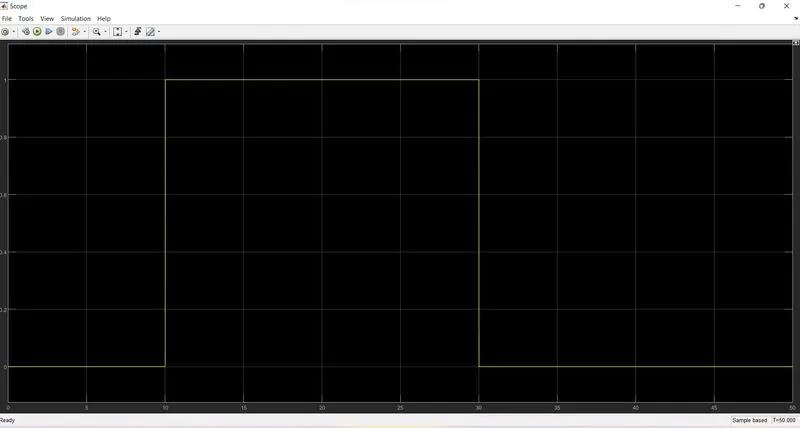
From the above fig we can observe that from 0-10 sec when the temperature is below 25 deg C the switch remains OFF and then for the next 20 sec when the temperature is above 25 deg C the switch is ON. Then after reaching below 25 deg C the switch is agained turned OFF.
This switch is can be connected to a fan to regulate it according to the condition.