Week -2
AIM- Make a Simulink model of Doorbell using solenoid block
Blocks are used in the model-
- Pulse Gernerator
- Simulink PS Convertor
- Scope (Input)
- Electric Switch
- Battery
- Solenoid
- Solver configuration
- Electrical refernce
- Mechanical Translational Reference
- Ideal Translational Motion Sensor
- PS- Simulink convertor
- Output Scope
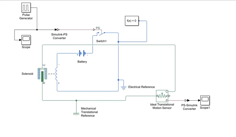
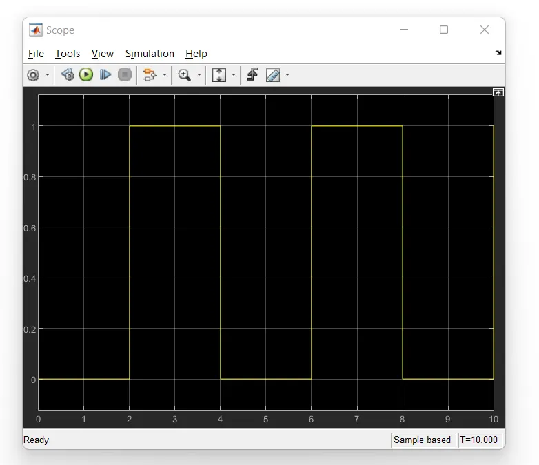
Model Started with input using pulse generator block with condition of our bell is engaged is for 2sec and then released the same putted the values of pluses inside block with 50% pulse width, phase delay 2s, period 4 sec with this input source is conncted to observe the pulses.
- solver configuration is conncted to the switch
- Battery is defined by for voltage source block
- Battery is conncted to switch and then conncted to the solenoid to complete the circuit
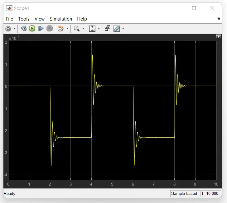
- solenoid is connected to an ideal translational motion sensor to observe the displacement by help of PS simulink convertor
- Mechanical or electrical refernce is provided for earthing
- stop time is given by 10s
2. Aim- Use a thermistor to sense the temperature of a heater & turn on or turn off the fan
Conditions- Temperature source: 20 °C from 0 to 10 seconds, 27 °C from 10 to 30 seconds, 23 °C from 30 to 50 seconds
Fan conditions: ON if the temperature above 25 °C, OFF otherwise
Blocks are used in the model-
- Repeating Sequence Stair
- Simulink PS Convertor
- Scope (Input)
- Controlled Temperature Source
- Solver configuration
- Thermistor
- Resistor
- Battery
- Voltage Sensor
- Controlled Switch
- Electrical refernce
- Mechanical Translational Reference
- Ideal Translational Motion Sensor
- PS- Simulink convertor
- Output Scope
- Lamp
When temp is above 298K
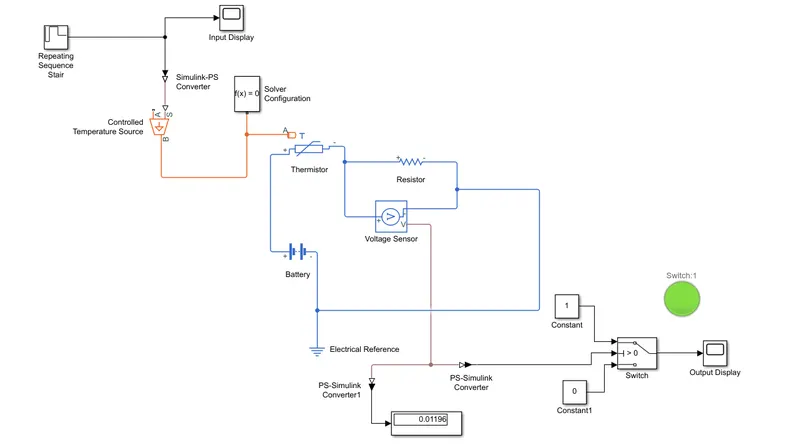
- Repeatiting Sequence Stair block is used for putting varying temperature values in kelvin. for observing the graph plots used input display convertor is used to conect controlled temperature source.
- Solver configuration is attched with controlled temp source point A of thermistor is conncted with temp source.
- thermistor is conncted with resistor and conncted with battery for complete the electric circuit.
- voltage sensor block conncted with thermistor and resistor voltage point conncted to conditional switch
- elctrical refernce is given for earthing
- Conditional switch is conncted to scope to display the graph and the output of switch is conncted to a lamp glows red if resistor across is less than the switch threshold meaning the fan is off simulatenously if resistor across is more than lamp will glows green
When temp is below 298K
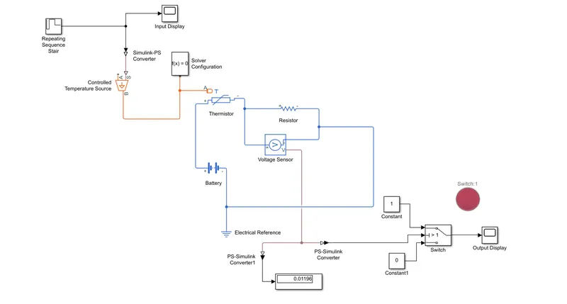
Lamp is in red (Fan is OFF ) ouput is comes 0
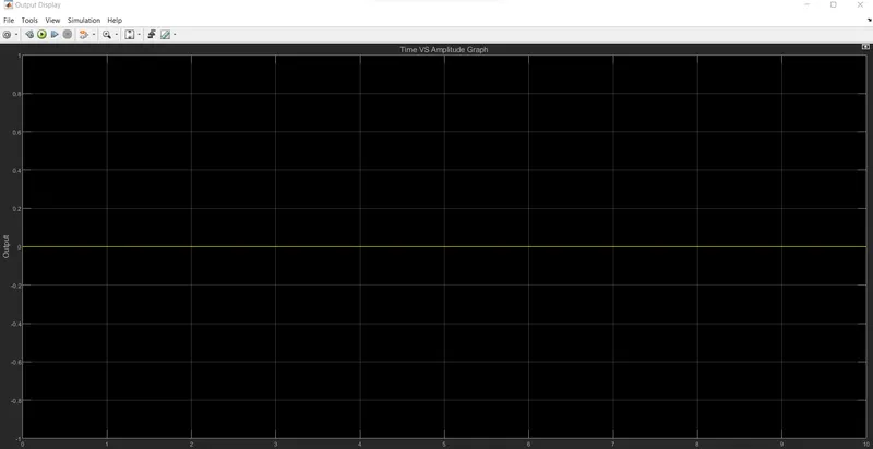
Lamp is in green(Fan is ONN ) ouput is comes 1