Week -2
Week 2:
- Make a Simulink model of Doorbell using solenoid block with the following details:
In the above arrangement, when the switch is closed the electromagnet receives electrical power from the battery and pulls the metal arm to hit the bell producing sound.
Create a situation where the switch is closed for 2 seconds and then released. Observe the physical movement of the plunger.
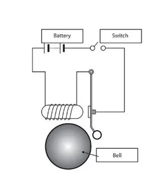 Fig 1: Sample diagram of Solenoid connected to Doorbell
>>Before moving to the Simulink model of Solenoid block, let's us understand brief about solenoid.
What is Solenoid?
A solenoid is a type of electromagnet formed by a helical coil (Cylinderal coil) of wire whose length is substantially greater than its diameter, which generates a controlled magnetic field. The coil can produce a uniform magnetic field in a volume of space when an electric current is passed through it.
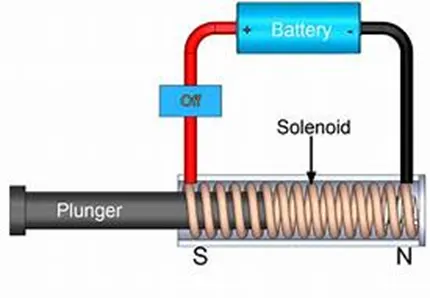 Fig 2: Solenoid working Explanation.
From the above figure we can simply say that when electrical current is introduced, a magnetic field forms around the coil which drawn the plunger in. Basically, it converts Electrical Energy into Mechanical Work.
Simulink model of Doorbell using solenoid block
Explanation:
Making a Simulink model of Doorbell using Solenoid block by using below parameters.
Required Parameter: Pulse Generator (Input), Switch, Battery, Solenoid block, Ideal translational Motion Sensor, Scope, Solver configuration.
Pulse Generator: We are using Pulse generator as an input because in the question we can see that they have mention switch has to be closed for 2 seconds and released automatically. Pulse Generator generate square wave pluses at regular intervals.
Pulse generator are used primarily for working with digital circuits.

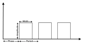
Here the waveform of pulse generator by giving required parameters, Amplitude, Pulse Width, Period, and Phase delay, determine the shape of the output Waveform.
Switch:
It's a device used to make or break the connection in a circuit and can be controlled manually or automatically depends on the type of switch required.
Battery:
Battery consist of one positive charged terminal and one negative charged terminal. Battery is a combination of two or more cells combined in series to produce higher electricity.

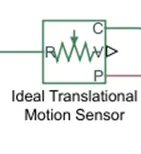
Ideal translational Motion Sensor:
It’s a sensor which provides the position or velocity input for the system to generate output.
Scope:
Give the Output in graph format in words it gives plot of the Output.

Solver configuration:
Compute the states of the model during simulation or code generation.
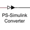
PS-Simulink Converter:
PS-Simulink Converter block convert physical signal to Simulink output signal.
Simulink-PS Converter:
Simulink-PS Converter block convert Simulink signal to physical signal.

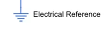
Electrical Reference block:
Represents an Electrical ground. Electrical conserving ports of all the blocks that are connected to ground must be connected to an Electrical reference bock. A model with electrical elements must contain at least one Electrical reference block.
Mechanical Translation Reference block:
Represents a reference block or frame, for all mechanical rotational parts. All rotational ports that are rigidly clamped to the frame (Ground) must be connected to a Mechanical Rotational Reference block.

Explanation of Simulink block Diagram
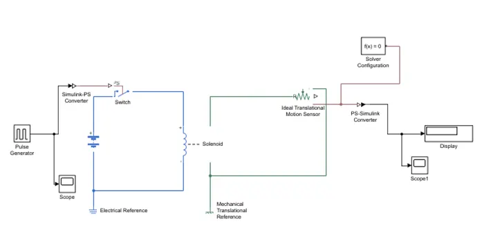
1.As we can see that solenoid block and battery model is connected to each other via negative and positive terminal in between a switch block is placed.
2. Now for switch to operate we need to provide physical signal through PS port in the Switch block. The provided physical signal should be greater than the threshold of the switch, for switch being close or else it will be open.
3. The Battery, Switch and solenoid path is connected to an Electric Reference Block Which represent earthing for the circuit.
4. Then we observe the solenoid block this "R" and "C" are two variable which represent Plunger and Fixed Point respectively.
5.solenoid block “R" is connected to "R" of Ideal Translation Motion Sensor Block which senses the position of plunger in the Solenoid Block and in the Ideal Translation Motion Sensor Block the output are given as "C" & "P" which represent the velocity and of the plunger.
6.Now "C" in the Ideal Translation Motion Sensor Block is a mechanical translation conserving port, which means that the mechanical process starts from "R" and end at "C” and again it starts at "R" and the cycle goes on. So "C" in the ideal translation Motion sensor block is connected to Mechanical Translation Reference.7. Similarly, "C" of the solenoid block is also connected to the same Mechanical Translation Reference as fixed point for solenoid.
8.Since we position of the plunger as output from "Ideal Translation Sensor Block we have connected port "p" to a PS-Simulink Converter where the Physical value from port is converted into Simulink value, and then this PS-Simulink Converter is connected to Scope Block which will generate a graph for change in position. Plunger from part 'P' of 'Ideal Translation Motion Sensor Block
9.Now to provide a physical signal for operating the switch, we have used a "Pulse Generator Block", which generates a continuous Square Pulse. So, we have connected a scope block to the Pulse Generator so that we can view the input accordingly.
10.From the below fig we can see that we have given
Period Value:4
Pulse width:50
Phase Delay:2 Sec
Amplitude:1(Default)
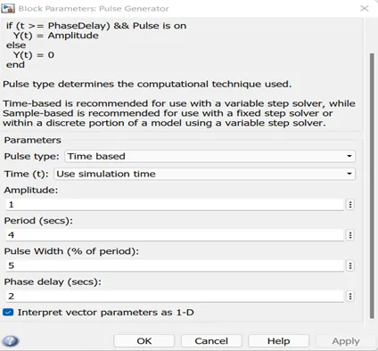
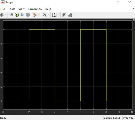
11.Initially the pulse will be Zero since we have given Phase delay as 2 so once it hit 2 sec the pulse will start rising from 0 to 1(Given Amplitude as 1). Now the pulse width will be half of period and for next 2 sec the pulse will be at amplitude 1 only.
12.It will again come down to zero once the pulse at 4 sec. For another 2 sec the pulse will be Zero so after these 2 secs of phase delay it will rise up thus cycle continues.
From starting to ending of the pulse it will take 4 sec of time period I which only for 2 secs the Amplitude will be “1” and for the rest of the time it will be “0”. So, after these 4 secs period again the pulse will be generated and thus Cycle continues.
13.Since the Pulse that is coming from Pulse Generator Block is a Simulink value, to convert value to Physical value we have used Simulink-PS Converter Block, since Switch only takes Physical value as inputs. As mention above, the port of Ideal Translation Motion Sensor Block is connected to another Scope2 and a Solver Configuration Block is also connected to this path which generates Equations and solves the whole Model internally to give the results of the Whole Simulink Model output. Now Run The Model and Double click on the Scope2 which is connected to deal Translation Motion Sensor Block to get the result.
14.Thus, this represents that when amplitude is the switch will be close and current will start flowing and when it is zero the switch will open and current stop flowing Since our objective is only to see the change in position of Plunger when Switch is Close for 2 sec, so we have the Amplitude as for 2 sec in the Pulse generator by making the Pulse width half of the period in the inputs for Pulse Generator Block.
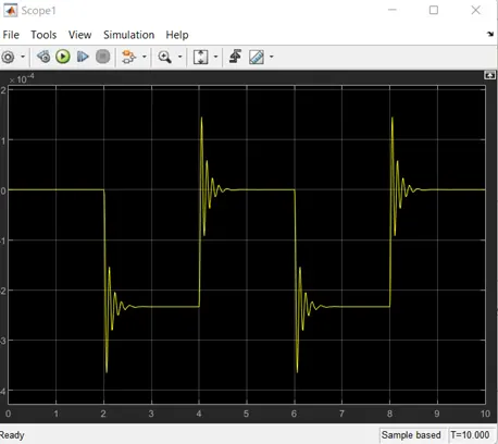
14.We can get smooth graph by changing the value of spring constant and damping co efficient value of solenoid.
2. Use a thermistor to sense the temperature of a heater & turn on or turn off the fan as per the below conditions:
Temperature source: 20 °C from 0 to 10 seconds, 27 °C from 10 to 30 seconds, 23 °C from 30 to 50 seconds
Fan conditions: ON if the temperature above 25 °C, OFF otherwise
Thermistor: A thermistor is a type of resistor whose resistance is strongly dependent on temperature, more so than in standard resistors. The word thermistor is a portmanteau of thermal and resistor.
Thermistors are divided based on their conduction model. Negative Temperature Coefficient (NTC) thermistors have less resistance at higher temperatures, while Positive Temperature Coefficient (PTC) thermistors have more resistance at higher temperatures Hence, a PTC thermistor's resistance is directly proportional to temperature.
NTC thermistor are widely used as inrush current limiters, temperature sensors, while PTC thermistors are used as self-resetting overcurrent protectors, and self-regulating heating elements. An operational temperature range of a thermistor is dependent on the probe type and is typically between −100 ⁰C and 300 ⁰C (−148 °F and 572 °F).
Signal Builder:
Signal Builder block allows you to incorporate test cases as a signal source in your model. Using the Signal Builder block you can: Graphically create and tweak signals using the signal builder interface.
Thermal Reference:
The Thermal Reference block represents a thermal reference point, that is, a point with an absolute zero temperature, with respect to which all the temperatures in the system are determined.

Voltage Sensor:
The Voltage Sensor block represents an ideal voltage sensor, that is, a device that converts voltage measured between two points of an electrical circuit into a physical signal proportional to the voltage.
Use the + and - ports to connect the sensor in parallel with the block (or several blocks) where you want to measure the voltage. Port V outputs the measurement result as a physical signal. Use a PS-Simulink Converter block to connect this port to Simulink® blocks, such as Scope or Display.

EXPLANATION:
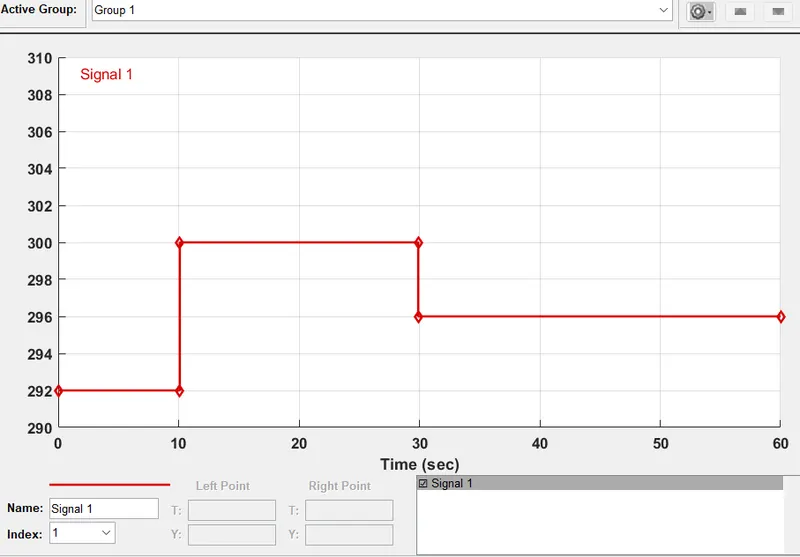
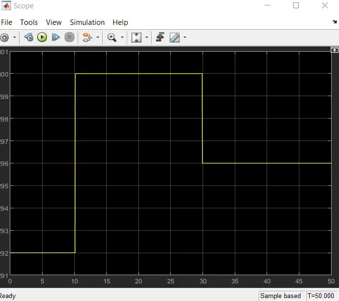
>>0-10 sec temperature 293
>>10-30 sec temperature 300
>>30-50 sec temperature 296
1.Initially above details are plotted on Signal Builder block where the input is inserted with these signals. As shown in the below fig.
Signal Builder is connected to Scope, observe the input plot in the below fig:
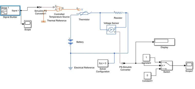
2.Before we run, we need to connect Simulink -PS converter block to be able to read the for system.
3. Now we need to set Simulink -PS Converter parameter.
>Filtering and derivatives: Filter Input, derivatives calculated.
>Input Filtering order: First-order filtering
>Input filtering time constant (in sec):0.001
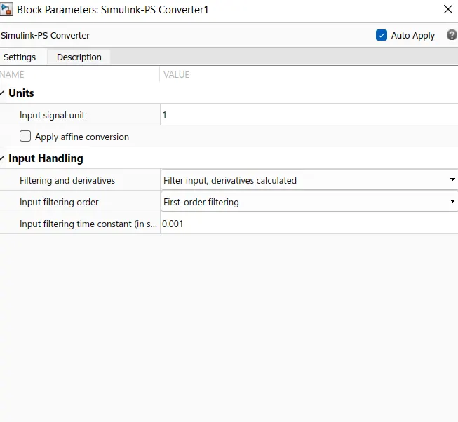
4.We can see in the fig that how different temperature are given at different time. So, thus we have created our signals and before connecting it to the controlled temperature source block we have to convert these signals into Physical value. So, to do this we have used a Simulink-PS converter.
5. Controlled Temperature Source Block
Port B is connected to port A of thermistor.
Port A is connected to Thermal Reference.
6. The negative port of thermistor block is connected to Resistor block and positive port of thermistor is connected to Battery block. Now Electrical Reference block is connected near the negative terminal of the battery block which represent the earthing of the real time circuit.
7. Now to represent a voltmeter a Voltage sensor block is connected parallel to the resistor block because to measure the voltage across a component, voltmeter should always connected parallel to that component.
8.Output terminal of voltage sensor is connected to switch. Using the switch parameter for giving the condition as Fan must be ON if the temperature above 298K otherwise is OFF.
9.The middle port of Switch Block is connected to output of PS-Simulink Converter which gives the Voltage values. The top port of the Switch Block is connected to a Constant Block of value '1' and the bottom port of the Switch Block is connected to another Constant Block of value '0'.
10.The Middle port of Switch Block is the condition input which means that when the value from Voltage Sensor Block is more than the Threshold value in the Switch Block then it will pass the value '1' which we have specified in the top port of the Switch Block. If the Voltage from the Voltage Sensor Block is less than the Threshold value in the Switch Block then it will pass the value '0' which we have specified in the bottom port of Switch Block.
11.To set the Threshold value of the Switch Block, we have to Double click on the Switch Block and then we can change the value of Threshold. Since we want to be ON only when the temperature is 300K so the Threshold value is given as 0.011. So when the Voltage gets more than "0.011" the Switch will give value '1' as output which means Fan will be ON and when Voltage get less than 0.011 the Switch will give value '0' as output which certainly means Fan will get OFF.
12.Now the output of Switch Block is connected to another Scope Block to get results.
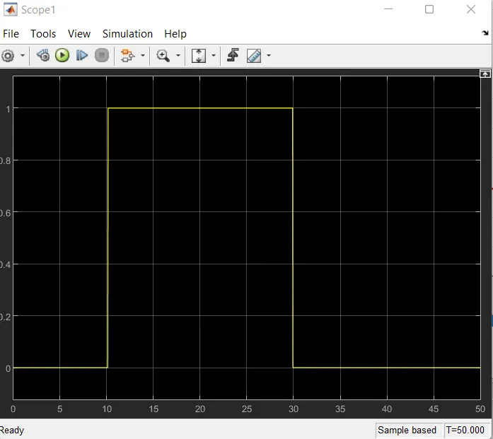
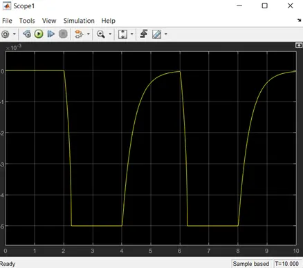
13.As view the output we can clearly see that for 0-10 secs fan is in OFF Condition because temperature is 298k. After 10 Secs temperature goes to 300K so the fan turns ON because temperature exceeds 298K. Again after 30 secs fan turns OFF because temperature goes to 296K which is below 298K.
CONCLUSION:
1.For both the model output is achevied successfully.
2.With simulink approach we can particularly improve the performance by analysing the plot and changing the configuration to obtain the better outcome.