Project
Project: Simulink for Mechanical and Electrical Engineers.
AIM: To study, analyse and make a detailed report on BAJA All-Terrain Vehicle model using Simulink and compare between model parameters.
OBJECTIVE: Prepare a technical report explaining the model properties & comments on the results.
>>
ALL TERRAIN VECHILE(ATV):
The term ATV stands for All Terrain Vehicle. It is also known as a quad or quadricycle type vehicle. An All-Terrain motor vehicle could have three, four or even six wheels. Unlike a motorcycle, generally, the ATVs have more than two wheels. This vehicle runs on low-pressure tires. However, it has handlebars instead of wheel for controlling the steering.
An all-terrain vehicle (ATV), also known as a light utility vehicle (LUV), as defined by the American National Standards Institute (ANSI); is a vehicle that travels on low-pressure tires, with a seat that is straddled by the operator, along with handlebars for steering control. As the name implies, it is designed to handle a wider variety of terrain than most other vehicles. Although it is a street-legal vehicle in some countries, it is not street-legal within most states, territories and provinces of Australia, the United States or Canada.
The riders ride an All Terrain Vehicle by siting on it just like a motorcycle. However, you don’t need much effort to balance it because extra wheels give more stability at slower speeds. Also, most dirt bikes are considered the ATVs because they are designed for off-road use only. Generally, most ATVs come with three or four wheels. However, some specialized applications require six-wheel models.
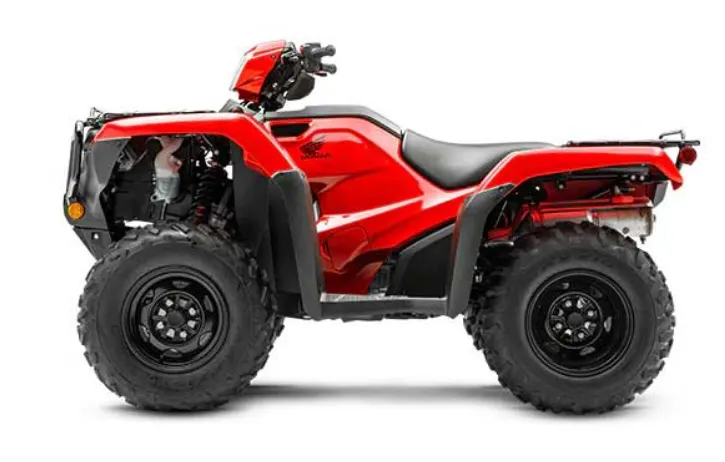
Generally, the intended use of All Terrain Vehicles is by a single operator only. However, some manufacturers make ATVs for use by two. Of them, one is the operator and other is passenger. So, manufacturers refer these ATVs as Tandem ATVs. The rider or main operator must wear a helmet just like a motorcycle rider. However, in some countries, it is not mandatory for the passenger to wear a helmet.
This project is reference to one of the types of ATVs used in BAJA SAE competitions.
BAJA SAE:
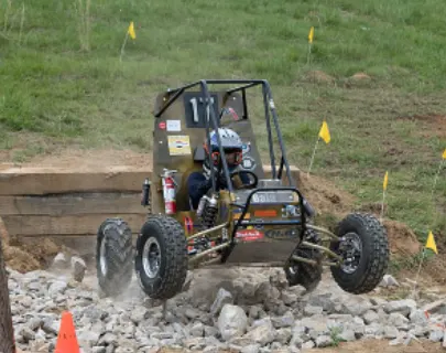
Baja SAE is an Collegiate Design Series competition run by the Society of Automotive Engineers International (SAE International). Teams of students from universities all over the world design and build small off-road cars.
The goal in Baja SAE racing is to design, build and race off-road vehicles that can withstand the harshest elements of rough terrain. The vehicles used in Baja SAE racing are often similar in appearance to dune buggies. Before 2007, the events were called "Mini Baja."
CASE 1:BAJA AVT Model
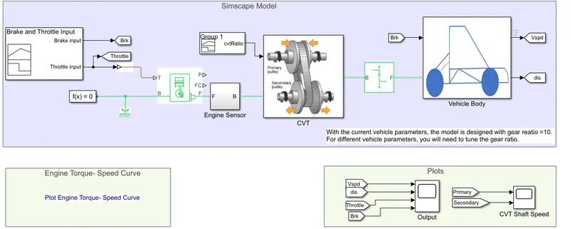
Equipment Required: Signal Builder, Goto, Simulink PS Converter, Generic Engine, Solver Configuration, Mechanical rotational reference, Engine sensor, PS-simulink Converter, scope, PS terminator, CVT, Simple Gear.
- Signal Builder:
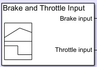
The Signal Builder block allows you to create interchangeable groups of piecewise linear signal sources and use them in a model. You can quickly switch the signal groups into and out of a model to facilitate testing. Our input signal is given in the signal builder (brake input and throttle input)
2.Goto:The Goto block passes its input to its corresponding From blocks. The input can be a real- or complex-valued signal or vector of any data type. From and Goto blocks allow you to pass a signal from one block to another without actually connecting them.

3.Simulink PS Converter:Converts the Simulink input signal to physical signals.

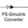
4.PS- Simulink Converter:Converts the physical input signal to Simulink output signals.
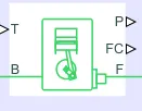
5.Generic Engine:The Generic Engine block represents a general internal combustion engine. This block is a suitable generic engine for spark-ignition and diesel. Speed-power and speed-torque parameterizations are provided. A throttle physical signal input specifies the normalized engine torque.
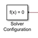
6.Solver Configuration:Compute the states of the model during simulation or code generation.
7.Mechanical rotational reference:Represents a reference block or frame, for all mechanical rotational parts. All rotational ports that are rigidly clamped to the frame (Ground) must be connected to a Mechanical Rotational Reference block.

8.Engine Sensor:
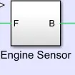
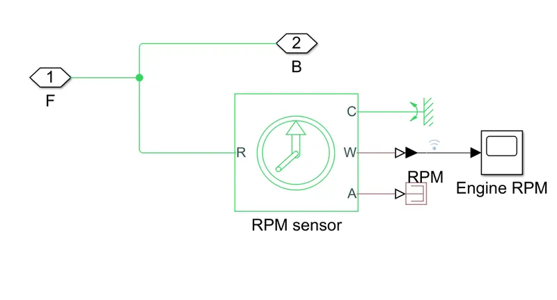
- Ideal Rotational Motion Sensor: The Ideal Rotational Motion Sensor block represents an ideal mechanical rotational motion sensor, that is, a device that converts an across variable measured between two mechanical rotational nodes into a control signal proportional to angular velocity or angle. You can specify the initial angular position (offset) as a block parameter.
- Scope: Give the Output in graph format in words it gives plot of the Output.
- PS terminator: This is used to terminate physical signal output.

CVT (Continuously Variable transmission drive):
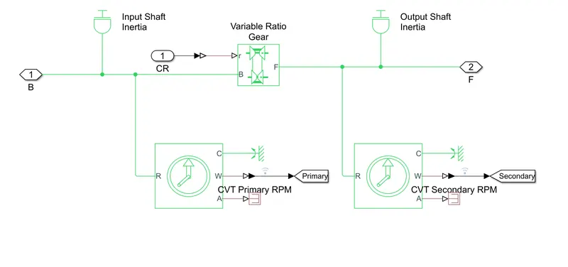
A CVT, or continuously variable transmission, seamlessly changes through an unending range of effective gear ratios while you drive, whereas other kinds of mechanical transmissions offer a fixed number of gear ratios and have hard shifts between each as explained by Certified Transmission Repair. CVT transmission systems are also known as single-speed, shiftless, and stepless transmissions. The shiftless nature of a CVT offers unparalleled flexibility that maintains constant angular velocity regardless of output speed. Additionally, a continuously variable transmission makes accelerating smooth and offers enhanced fuel economy.
How Does a CVT work?
While a traditional transmission uses a wide variety of intricate parts to shift between a range of pre-set gears, most CVT systems work through a pulley system. In short, this system consists of cones at each pulley connected via a chain belt. The cones can move to increase or decrease the belt diameter to change gear ratios, allow for quick shifting into the needed ratio for increased power, and boost fuel economy.
One pulley in the CVT is connected to the engine and the other directs power to the wheels. The width of these pulley’s changes based on the needed power; as one gets larger, the other gets smaller. There is a second, less common, type of CVT that uses a series of discs and rollers, but it operates on similar principles.
Though there are no gears in a CVT, some simulate a more traditional changing of gears. In these transmissions, the belt-and-pulley system is designed to move to pre-set points by using a traditional shift lever or paddle shifters on the steering wheel.
Variable Transmission ratio:
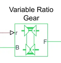 Represents a variable ratio gearbox such as implemented by mechanical belt CVT, electric or hydraulic transmissions. The physical signal input ‘r’ defines the ratio of input to output angular shaft velocities. Connections B(base) and F(follower) are mechanical rotational conversing ports. Specify the relation between base and follower rotation directions with the Output shaft rotates parameter.
IX). Simple Gear:
Simple gear represents a fixed ration gear or gearbox.

X). Vehicle Body-CVT
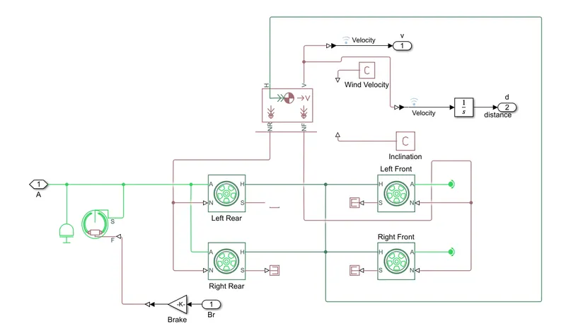
- Inertia: Represents an ideal mechanical rotational inertia
- Tire: Tire with longitudinal behaviour given by magic formula Coefficient.
- Double Shoe Brake: Represents a frictional brake with two pivoted rigid shoes that press against a rotating drum to produce a braking action.
- Integrator: This block represents output value of the integral of its input signal with respect to the time.
- PS Constant: This block creates a physical signal constant.
- From: This block accepts a signal from a corresponding Goto block, then passes it as output. The data type of the output is the same as that of the input from the Goto block. From and Goto blocks allow you to pass a signal from one block to another without actually connecting them.
INPUTS OF MODEL:
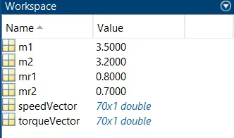
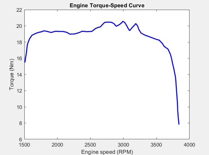
- The variable m1, m2, m3 stands for the mass input for the inertial at input shaft and output shaft at CVT. The variable ‘speedVector’ and ‘torqueVector’ are the engine parameters for the Generic engine. This Generic Engine us the relation between torque and rpm of the engine.
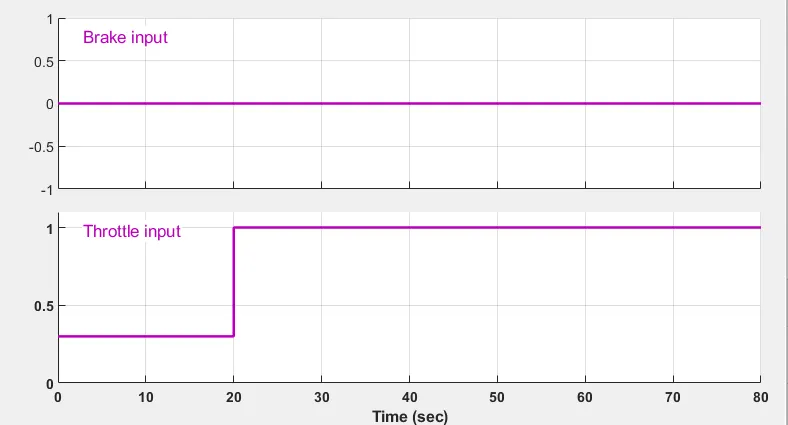
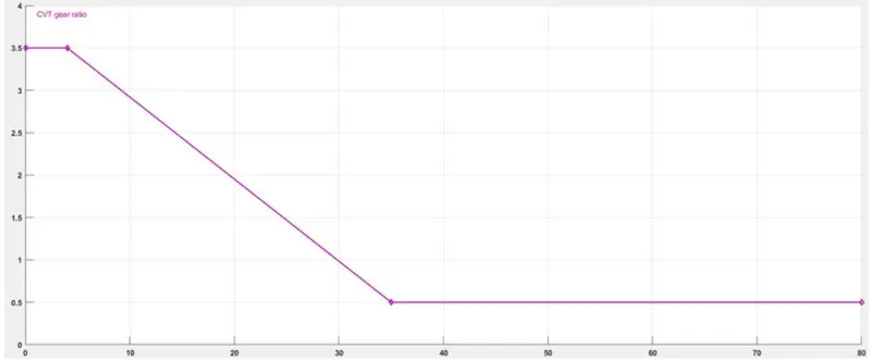
- To signal Builder we have given a throttle input and brake input and also CVT ration is changed with w.r.to time.
ii).CVT ratio
iii)Torque vs Engine speed input
OUTPUT OF VEHICLE SPEED:
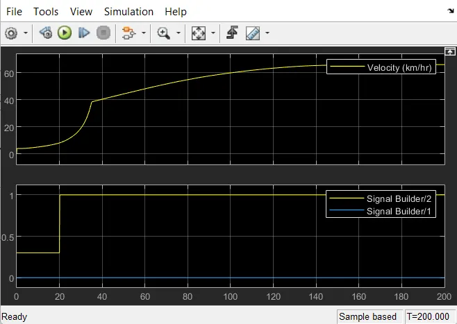
From the output we can view that when throttle input is at 0.3 for 20sec speed of the vehicle increases correspondingly and full throttle=1 the vehicle speed jumps to nearly 40kmph and then spontaneously goes on increasing.
CVT SHAFT RPM: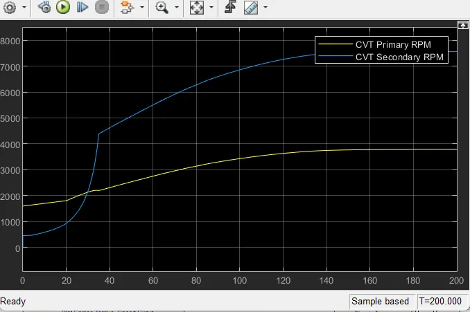
Graphs shows the variation in angular velocities of input and output shafts of the variable gear transmission system. These values differ w.r.to gear ratio.
CASE 2:
BAJA ATV MODEL WITH LOOKUP TABLE
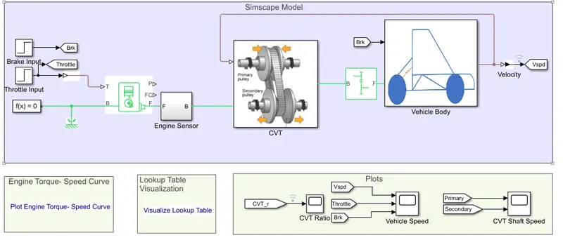
This model is similar to previous model only difference is CVT ratio is provided in lookup table.
Lookup table:
- A lookup table block uses an array of data to map input values to output values, approximating a mathematical function. Given input values, Simulink performs a “lookup” operation to retrieve the corresponding output values from the table.
- In the Model input is already is uploaded in the formed of lookup table.
- Simulink perform a lookup operation to retrive the corresponding output values from the table, If the lookup table does not define the input values, the block estimates the output values based on nearby table values.
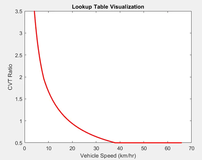
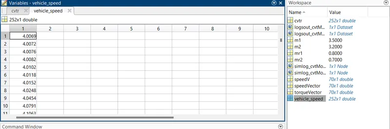
Below fig show the workplace where lookup table values are stored.
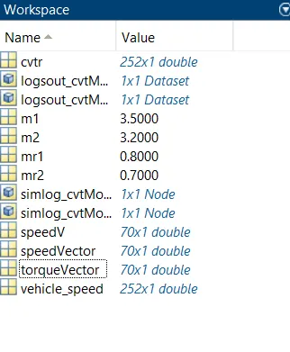
CVT ratio:
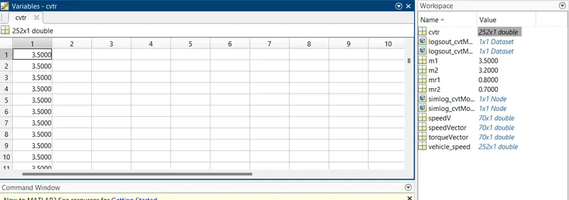
Vehicle Speed Data:
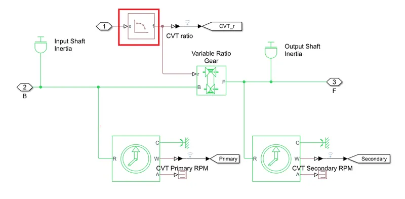
CVT Model With lookup block.
The input to the model (brake and throttle) is provided in step time, it depend on run time and its varies accordingly. By using lookup table for the gear ratio and it gives input to CVT Block.
In the model the input values are given by lookup table and accordingly the output values are obtained.
From the CVT Model: The red rectangle high lighted block as Lookup table block. Input Shaft represents the primary pulley and output pulley represents the secondary pulley, mechanical rotational sensor is connected to input and output shafts and variable ratio Gear represents a variable ratio gearbox such as implemented by mechanical belt cvt, electric or hydraulic transmission. The physical signal input r defines the ratio of input to output angular shaft velocities. Connections B(base) and F(Follower) are mechanical rotational conserving ports. Specify the relation between base and follower rotation directions with the output shaft rotates parameter. CVT ratio is obtained from the lookup table.
OUTPUT:
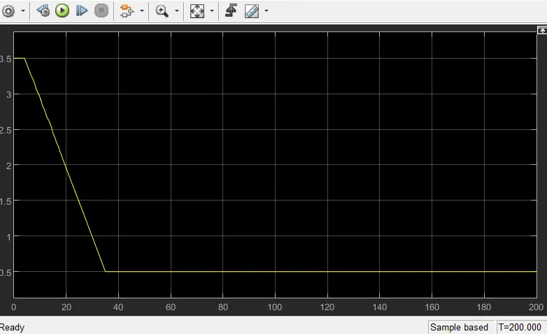
CVT Ratio:
The data is obtained from lookup table
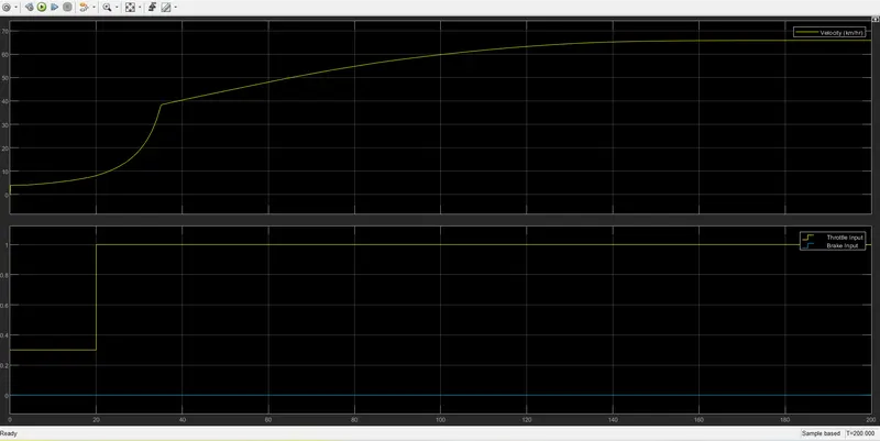
Vehicle Speed:
From the output we can view that when throttle input is at 0.3 for 20sec speed of the vehicle increases correspondingly and full throttle=1 the vehicle speed jumps to nearly 40kmph and then spontaneously goes on increasing.
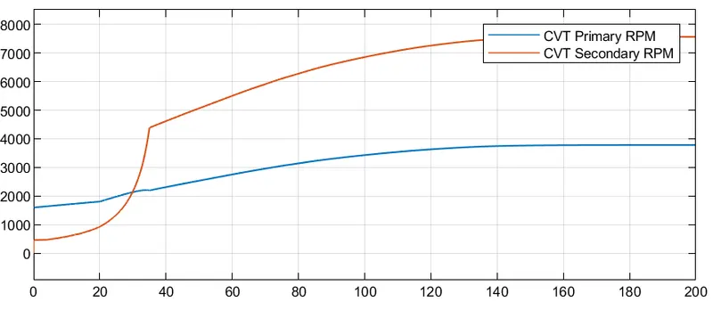
CVT Speed:
Graphs shows the variation in angular velocities of input and output shafts of the variable gear transmission system. These values differ w.r.to gear ratio.
CASE 3:SIMULINK MODEL FOR BAJA ATV WITH CVT USING DASHBOARD:
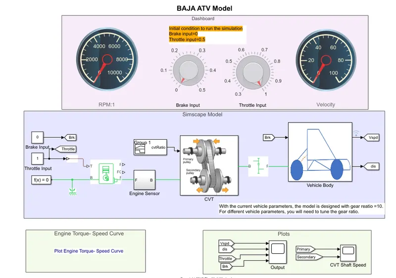
i)This model is similar to earlier only difference here is we change the throttle and brake value during the simulation is running and then we can observe it’s results. And additional equipment added in the model is explained below.
ii). Knob: We can set a value and tune the parameter as per our preference.
iii).Circular Gauge: Display the input value and it’s a customized gauge.
CVT ratio:
RESULTS:
ENGINE RPM:
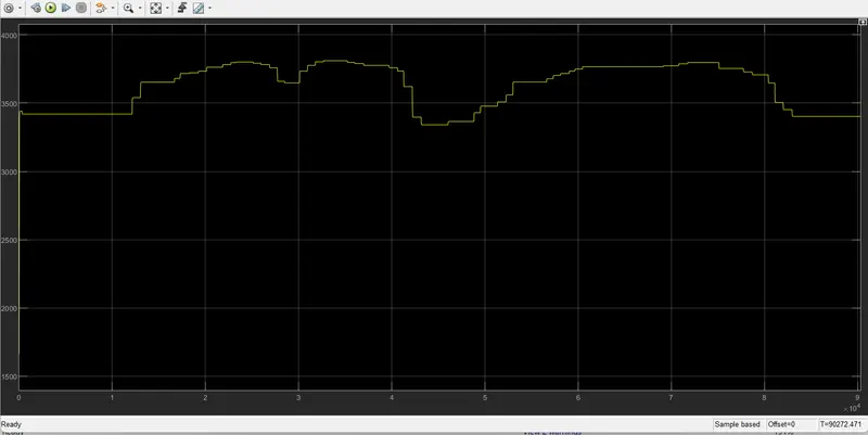
We can observed that by increasing the throttle input value, it will increase the engine speed and by increasing the brake input value it will decrease the Engine Speed.
VEHICLE SPEED:
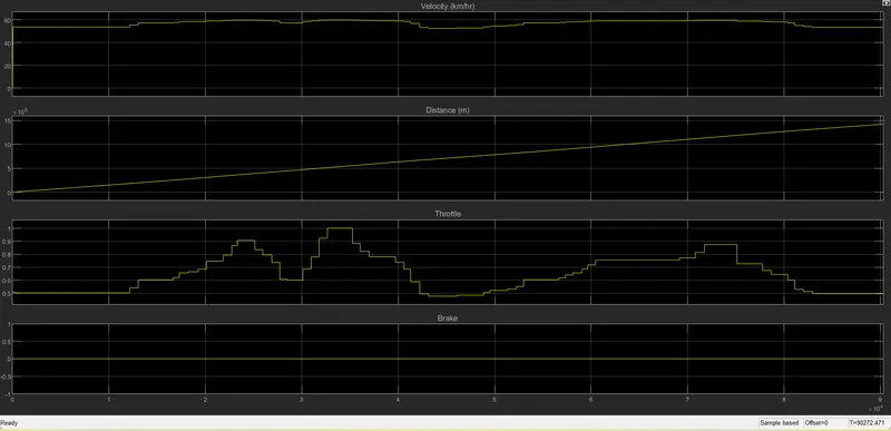
From above output we can observed that by increasing the throttle input value, it will increase the velocity and by increasing the brake input the velocity will decreases. We are varying throttle input through knob correspondingly we can view the variation in velocity of vehicle.
CVT SHAFT SPEED:
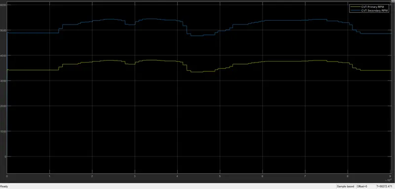
We can observed from above outputs that velocity of vehicle and CVT secondary RPM behaves same because secondary pulley is connected to vechile output and also we can view that by increasing the throttle input, it will increase the RPM of the promary and Secondary pulley and by increasing the brake input value it will decrease the RPM of the primary and secondary pulley.
CASE 4:SIMULINK MODEL FOR BAJA ATV WITH CVT USING DASHBOARD AND LOOKUP TABLE:
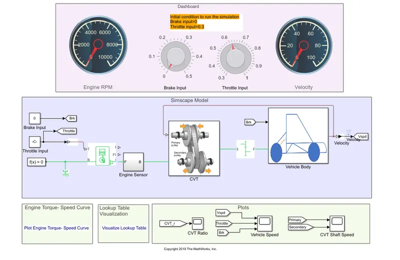
This model is similar to previous model with lookup table the only difference here is that the input signal is given through knob in dashboard and corresponding the velocity id observed.
Visual Lookup table:
OUTPUTS:
CVT RATIO:
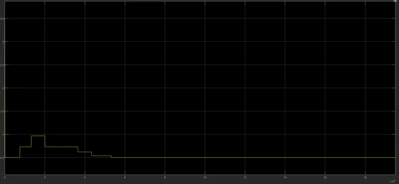
In the above plot, CVt ratio will vary by changing the throttle gauge, if the throttle value increases the CVT ratio decreases and if the throttle value decreases the CVt ratio increases.
VEHICLE SPEED:
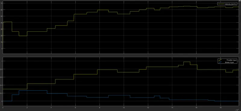
From above output we can observed that by increasing the throttle input value, it will increase the velocity and by increasing the brake input the velocity will decreases.
CVT SHAFT SPEED:
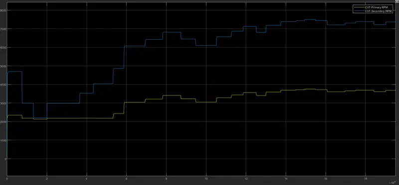
We can observed that by increasing the throttle input, it will increase the RPM of the promary and Secondary pulley and by increasing the brake input value it will decrease the RPM of the primary and secondary pulley.
ENGINE SPEED:
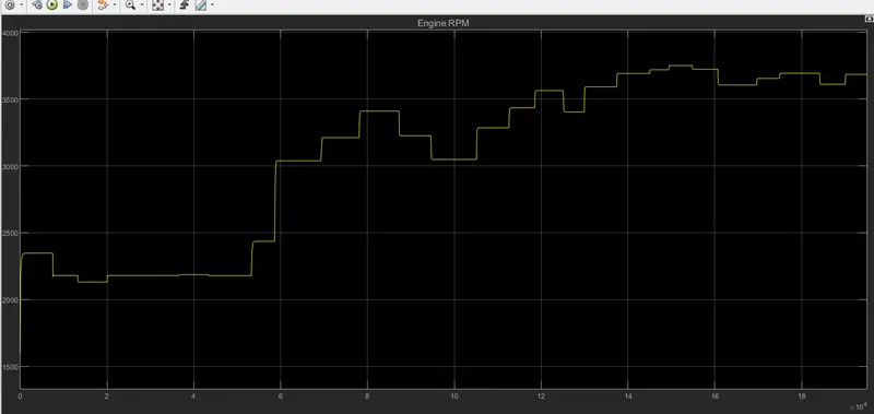
We can observed that by increasing the throttle input value, it will increase the engine speed and by increasing the brake input value it will decrease the Engine Speed.
CONCLUSION:
>>We have successfully achieved the output result for BAJA All terrain Vehicle model with 4 different cases.
>> Through this model we can understand how the vehicle may perform under the provided Conditions.
>>This model helps us to verfiy the performance of the vehicle under the constructed brake system and throttle system.