Week -2
- Make a Simulink model of Doorbell using solenoid block with the following details:
Here is the simulink model of doorbell using solenoid.
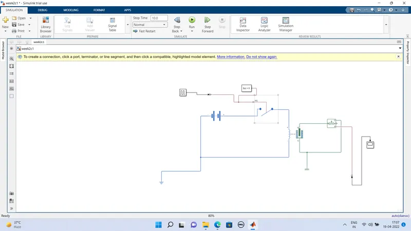
Explanation:
A pulse generator is given as input with following specifications.
Amplitude=1
Period=4 seconds
Pulse Width=50% of 4 seconds
Phase Delay= 2 seconds
A signal from pulse generator is converted to physical signal by using PS simulink converter and given as input to switch. A solenoid is used and battery is connected. The voltage in battery is same as rated voltage of solenoid. Ideal transitional motion sensor is used to measure the position of solenoig plunger. Electrical and Mechanical references are connected with the respective ciruits. The output of Ideal transitional motion sensor is converted using PS converter and connected to input of scope. Scope is used to view the output.
Output:
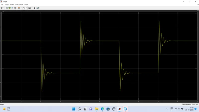
Run time is 10s.
For every interval of 2 seconds, the switch is turned on and off.
2. Use a thermistor to sense the temperature of a heater & turn on or turn off the fan as per the below conditions:
Temperature source: 20 °C from 0 to 10 seconds, 27 °C from 10 to 30 seconds, 23 °C from 30 to 50 seconds
Fan conditions: ON if the temperature above 25 °C, OFF otherwise
BLOCKS USED:
Signal builder- To generate signal according to given input.
PS-simulink converter- Convert simulink signal to physical signal.
Controlled Temperature Source- It would provide temperature output signal based on given input.
Thermistor- It shows the relation between temperature and resistance.
Battery- Battery is a storage device which would produce energy based on parameters given.
Resistor- Resistor would provide opposing nature of current in a circuit.
Voltage sensor- It is used to meausre voltage or potential difference between electrical components.
Switch- Switch is used to perfom ON and OFF condition of fan based on given input.
Scope- Scope is used to obtain output in graph.
Here is the simulink model:
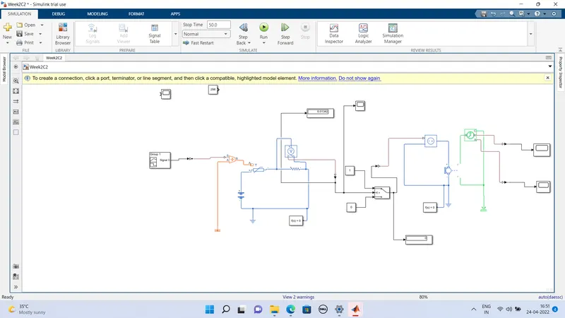
Inputs are given to the signal builder and it is connected to controlled temperature sensor through simulink-PS converter which can used to convert simuling input signal into physical signal.
- A positive terminal of voltage source connected with positive terminal of thermistor and thermistor connected with resistor. A negative terminal of voltage source connected with negative terminal of voltage sensor and negative terminal of resistor.
- The input temperature flows through resistor and the temperature controlled source is used to maintain specific temperature value.
- A switch is used to perform ON and OFF conditions fan. The output of voltage sensor is given as input to switch to turn ON fan if the temperature is greater than 25 C and turn OFF fan if it is lesser than 25 degress.
- A scope is used to obtain output in waveform or in graph.
INPUT:
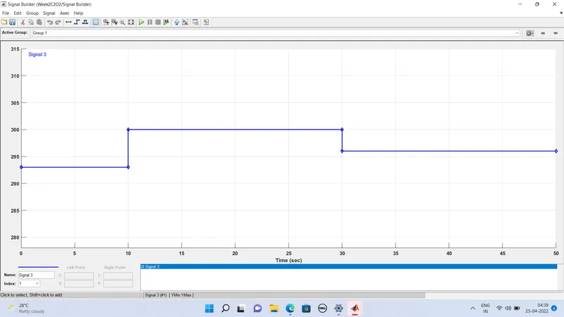
The given input conditions are:
Point 1: Time: 0 sec ; Temp: 293K
Point 2: Time: 10 sec ; Temp: 293K
Point 3: Time: 10 sec ; Temp: 300K
Point 4: Time: 30 sec ; Temp: 300K
Point 5: Time: 30 sec ; Temp: 296K
Point 6: Time: 50 sec ; Temp: 296K
OUTPUT:
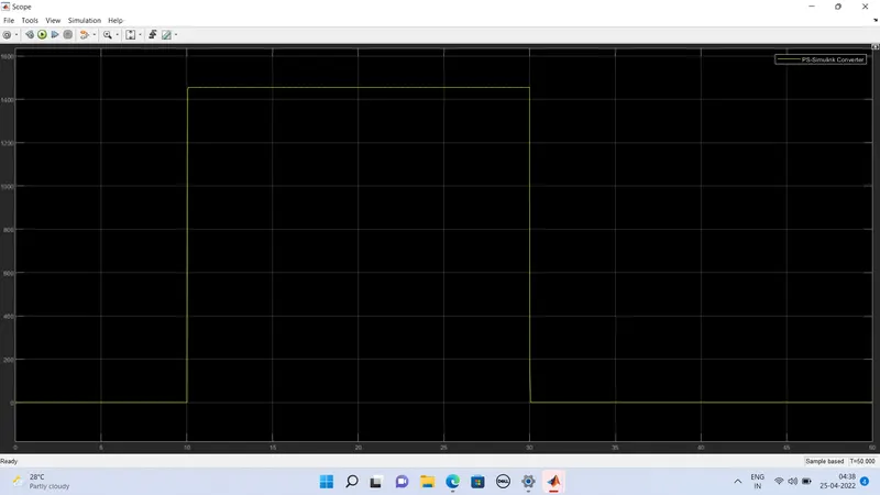
The fan is OFF from 0-10 seconds as the temperature is 20 °C.
The fan is ON from 10-30 seconds as the temperature is 27 °C.
The fan is OFF from 30-50 seconds as the temperature is 23 °C.