Project
AIM:
To prepare a technical report of All-Terrain Vehicle (ATV) Model.
Objectives:
Carry out a system-level simulation of an all-terrain vehicle and prepare a technical report explaining the model.
Simulink Model:
Description:
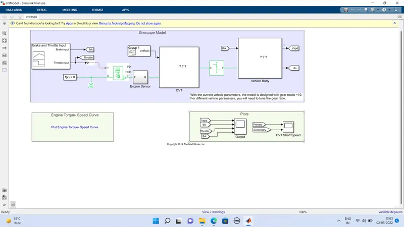
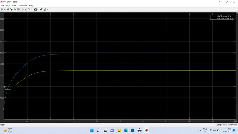
This model shows the simulation of ATV vehicle with input as a constant from signal builder and output of velocity and brake of the ATV vehichle with the rpm speed of the shaft.
The signal for brake input and throttle for engine is given to generic engine. The generic enging block takes the input of throttle and rotation of shaft accordingly. The shaft from generic engine block connected to engine sensor which indicated the speed of the shaft. The shaft is also connected with simple gear. The simple gear reduces the speed of the shaft to certain value and connected to CVT system.
The CVT subsystem is used to change the speed of the pulley with the help of the simple gear ratio. The vehicle body calculated the velocity of vehicle and shows the result in scope.
Signal builder:
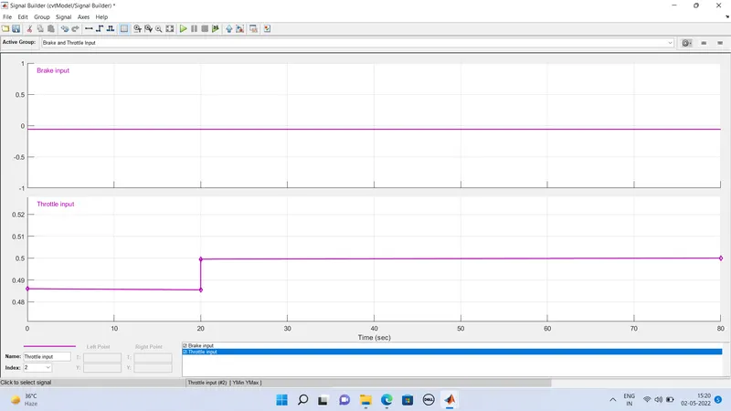
Signal builder is used to give input for brake, throttle and CVT gear ratio. Signal builder also used to give the input to the ATV vehicle. CVT gear ratio develops signal for variable gear ratio which determines vehicle speed.
Generic Engine:
The generic engine gets the input from throttle signal and works accordingly. The engine base (B) is connected to the mechanical reference block. The crank shaft rotates (f) based on the input of throttle and connected to the sensor. The generic engine is operated with prdefined values of torque, speed, inertia, etc.
Ideal Rotational Motion Sensor:
This sensor measures the rotation movement of engine shaft. It gives output of velocity and displacement. This velocity is taken as RPM of engine and displayed in scope.
Mechanical Rotation Reference:
It can be connected anywhere in the mechanical circuit, it is mandatory to use when rotationl-related components are used.
Simple gear:
Simple gear is a fixed value, it changes speed to a certain level. It can also change the direction of the speed.
CVT subsystem:
CVT subsytem is used to change the speed of the shaft in wider range.
Vehicle Body Subsystem:
It consisit of Vehicle body block, tire and Double-shoe brake.
Vehicle body block:
Using this block, we can specify the vehicle mass, number of axle per wheel, distance of axle from center, height of vehicle, wind velocity, inclination of vehicle etc.
Constant values are given to the parameters.
Double Shoe brake:
The break from input signal is connected to double-shoe brake with gain of 1000.
The double-shoe brake's other end is connected to the rotating shaft, when the input value increased the brake reduces the speed of the shaft.
Tire:
Tire block represents tire in the vehicle. We can specify the inertia, stifferens, damping etc.
Scope:
Scope is used to get output.
OUTPUTS:
MODEL 2 using Dashboard:
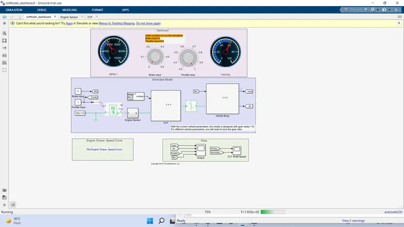
In model 2, we can change the input parameters by using dashboard block, in model 1 input is constant from signal builder.
In model 2, we can visually understand the change in output according to input with the help of dahsboard, in model 1, output can be viewed only through scope.