Week -2
1. Simulink model of doorbell:
Fig a:
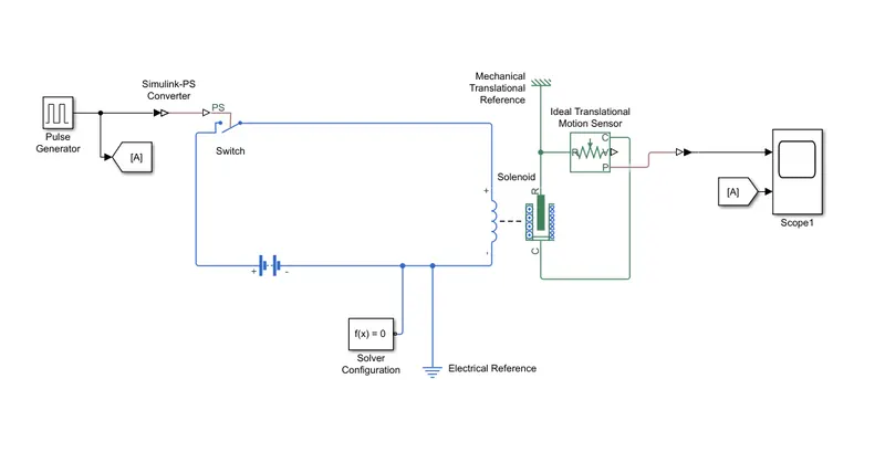
The goal of bell ringing is achieved by means of a plunger connected to solenoid that moves when the solenoid gets excited. The same is simulated as shown in fig a above.
- The battery is used as a voltage source which when connected to a solenoid block ports to continuous excitation which locks the plunger in actutated position. For the purpose to be achieved, the plunger must move in a reciprocating fashion.
- To Achieve the same, a switch block is connected in series which is in turn connected to a pulse generator.
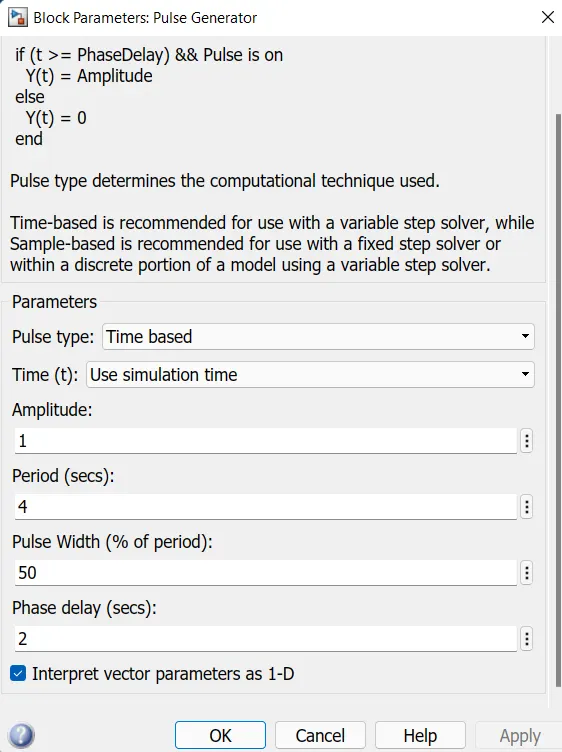
- To generate the pulsed activation of solenoid, a pulse generator is configured according to the Fig b which is given as input to switch with a delay of 2 sec
- To realise the movement achieved by the plunger of solenoid, an Ideal Translational Motion Sensor is connected to the actuation port of the solenoid.
- The output of which is connected to scope1 for visualisation of results.
- for facilitation of comparision of input and output, the output from pulse generator is also connected to the scope1
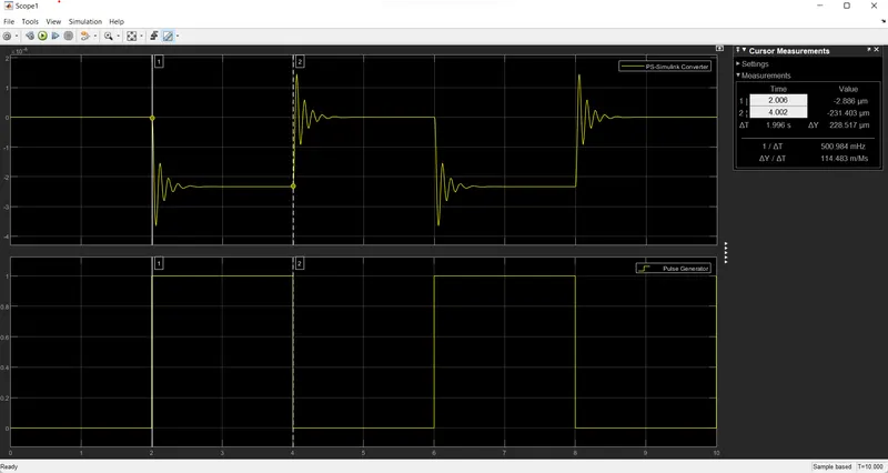
- The Input, Pulse and Time delay and the Output, position of plunger and the time delay are visualised in Fig c below (The negative values can be ignored as the change of position is priority here rather than the direction)
2. Using Thermistor and Switching the Fan based on Temperature:
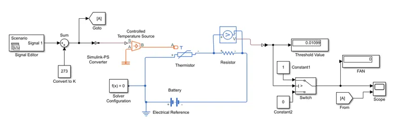
The aim of this model is to simulate the sensing the temperature of a given system and switching the Fan to cool the system when a preset valuse is crossed.
Fig a below shows the schematic of the model:
Fig a
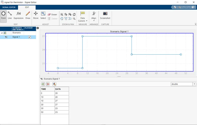
- The required profile of input temperature( in celcius) is obtained by using a signal editor block as shown in fig b.
fig b
- The output from signal editor is converted by Simulink PS converter and is fed as input to the controlled temperature source block which gives a steady output as received in the input without any effect of heat flown across.
- As the profile is made in celcius to convert it into Kelvin a Sum block is used where constant value of 273 is added to the output of signal editor
- hence the output of controlled temperature source (in kelvin) is fed as input to the physical port of the Thermistor block which is connected to a battery as a voltage source.
- A resistor is connected and voltage across the resistor is monitored intially to know the threshold value of the thermistor which is shown in threshold Value display block
- to achieve the switching process, a swtich is connected with 3 inputs, 1st to a constant 1 which signifies ON condition upon satisfying the condition in 2nd input which is the Threshold value. 3rd input gets activated once the condition at port 2 fails.
- The switching ON/OFF of the fan is visualised in the FAN block which shows 1 when ON and 0 when OFF.
- The same can be visualised in a Scope block as final output to which the output from sum block is also given as input which is shown in fig c
fig c
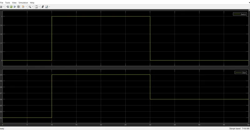
Hence it can be concluded that as and when the voltage crosses the threshold value of 0.01099 i.e 25 degrees celcius, the FAN is Switching ON (FAN value 1) and when below 0.01099 it is Switching OFF