Project
AIM:
The aim of this model is to simulate the characteristics of the Baja ATV vehicle by varying the throttle and the cvt gear ratios by employing various modes and checking the performance of the vehicle by the outputs like distance travelled, throttle, brake and the velocity of the vehicle.
Mode1: using a fixed set of gear ratio chart
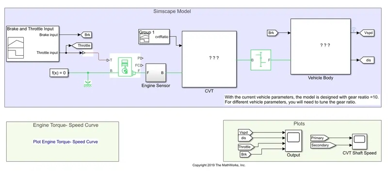
Here in this CVT model we can observe that it is divided into three main segments.
One is the input segment which consists of the throttle and brake
and next is the CVT block which is a subsystem containing the transmission part and
next is the vehicle body which gives the overall output.
- Coming to the input section, if we check under the mask of this break-in throttle input, it is basically a signal builder with a preset signal for brake at zero, which means that the brake lever is not pressed and the throttle at 0.5 which indicates the 50% of the maximum torque which can be increased gradually to 1 which is 100% of max torque
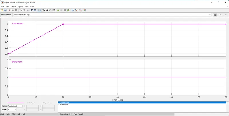
The output from this block would be the throttle and the brake. The throttle output, which is fed to the generic engine block.
If we look under the generic engine simscape block, we can put the input parameters like speed vector, torque vector which can be derived via the variables and other limits like speed threshold, fuel consumption. They all can be said to be default.
he output in the form of rotational moment is given via the f output port which becomes the input for the engine sensor block which has basically an RPM sensor that converts the input rotations into a measurable format via the w port which is then again converted into a simulink format and is displayed via the engine RPM scope from the same. The output is also taken
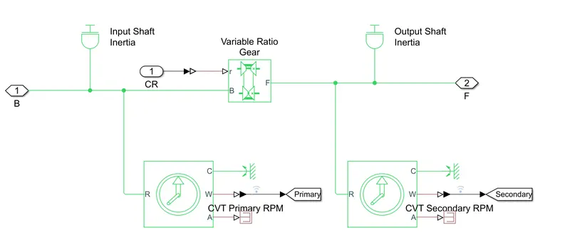
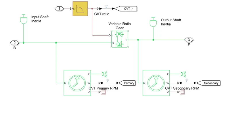
- Now coming to the transmission part here a CVT transmission is being used which has primarily two inputs. One is the RPM of the crank shaft and the second one is the gear ratio. Basically a CVT gear ratio which has been imported to the signal builder lock via an Excel file. So the gear ratio with respect to time is changing as per the profile. As one can see inside this CVT mask that there are two variable transmissions, the primary and the secondary the primary which is connected to the engine and then the variable gear ratio for which the output is in the form of signal builder format. The output of this variable gear ratio is given to the CVT secondary, which is in turn the output of the CVT block
A simple gear block is used to ensure the to simulate the differential. In this case the gear ratio of this block is given as 10 :1. The same is fed now to the vehicle body
The vehicle body represent a two axle vehicle body in longitudinal motion.
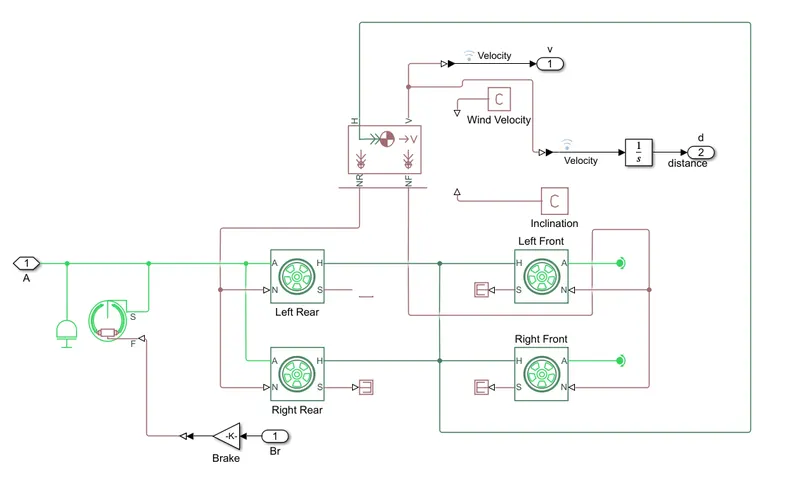
The block accounts for body mass aerodynamic drag road incline and weight distribution between axles due to acceleration and road profile. It has the following as input ports which are normal reaction from the tires of the rear and of the front and the inclination which is a PS constant block which is a dummy value. Same is with the wind velocity which is given some constant value. In this case, those are irrelevant as one can see the edge port which represents the mechanical translational conserving port associated with the motion of the vehicle. He is connected to the wheels. The wheels which are four in number, both two in the front and two in the rear are connected to the edge port of the vehicle body
The rotations from the gearbox block which is indicated by the f port in the simple gear block is used as an input for the vehicle body which sends the energy to the wheels.
The wheel block represents the longitudinal behavior of a highway tire and the block is built from the tire road interaction and simscape foundation library, wheel and axle blocks. Optionally, the effects of tire inertia stiffness and damping can be included. As one can see the rotational energy from the gearbox is connected to the left rear and right rear wheels with signifies that this is a rear wheel drive and the translatory motion generated by the wheel is transmitted through the edge port to the to both the left front and right front wheels, thereby simultaneously to the edge port of the vehicle body. The vehicle body then calculates the velocity with the prebuilt governing equations and the velocity is sent via the output we port which is then converted to simulink format by PS simulink converter from the velocity. The distance is calculated by using the integrated block which can be used as the output for the braking mechanism. A double shoe brake in tandem with the rotational energy from the gearbox. The brake force can be applied using the physical export of the double shoe brake block which is the input which is given by the brake block which is there in the input section and happens to be the output of the signal builder.
RESULTS:
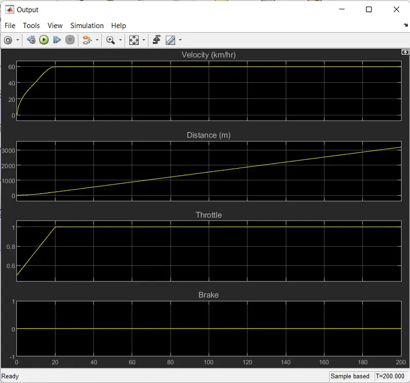
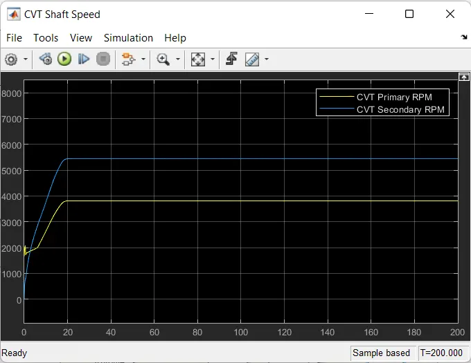
Generally, the above case of fixed cvt ratio is impractical and hence to make it more realistic following models are built.
MODE2:
Varying the gear ratio using dashboard like setup in simulink:
This can also be done using the following model
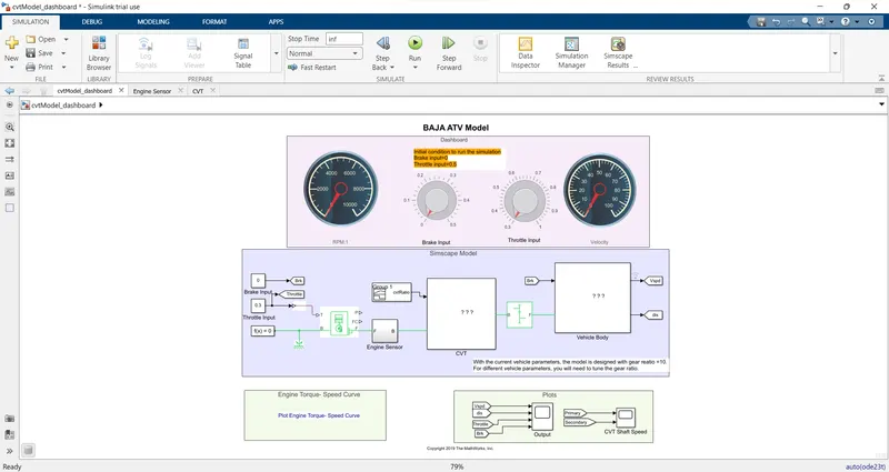
Here the sim time is infinite and the knobs of brake and throttle can be varied along the simulation
REULTS:
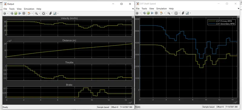
the throttle and brake knobs are varied through out the simulation
MODE 3:
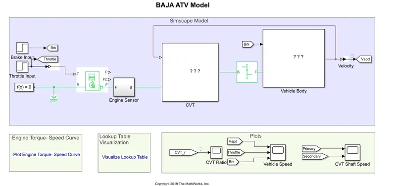
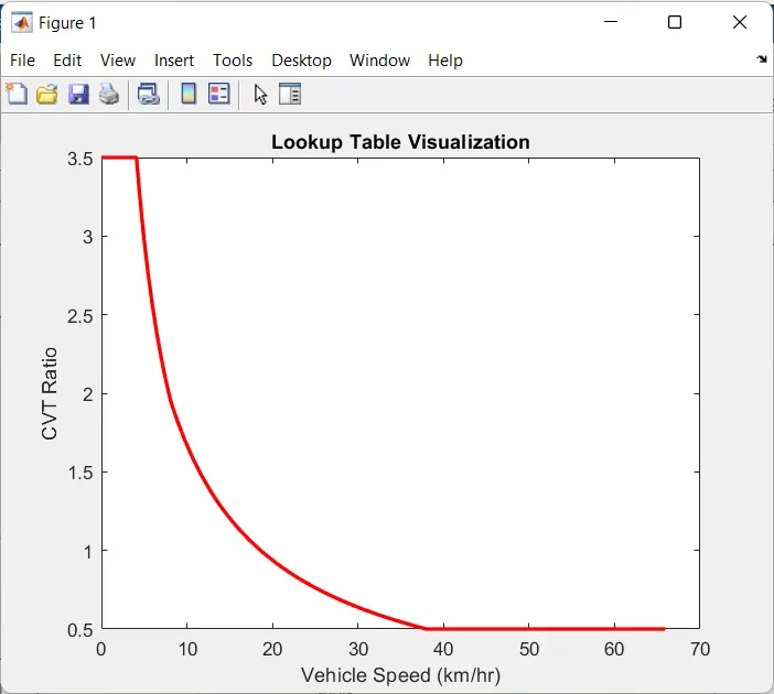
Varying CVT ratio using the lookup table:
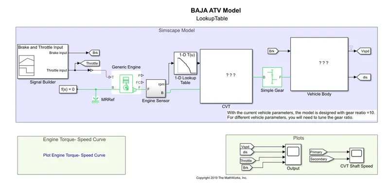
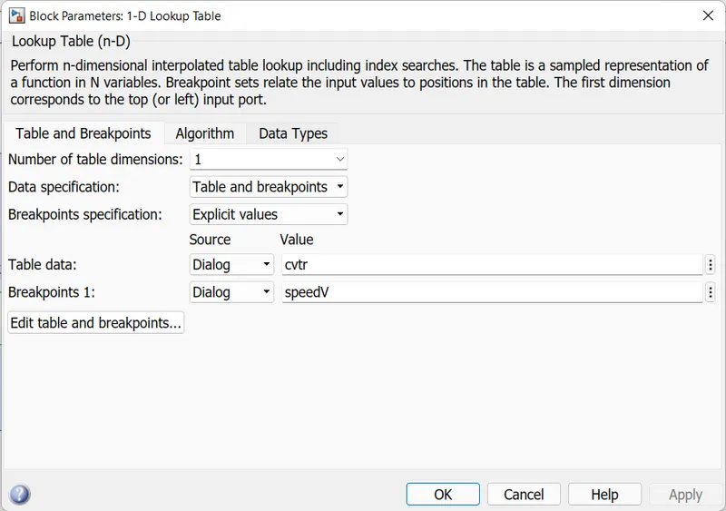
The variables are predefined in mat file format from where they are added in the workspace.
RESULTS:
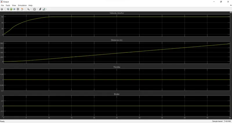
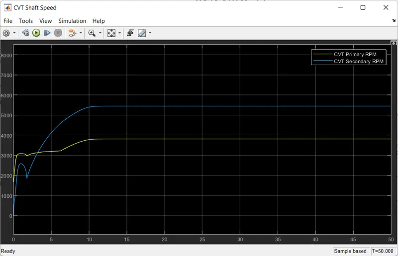
The mapped lookup table has also been used as shown below