Week 2- 2R Robotic Arm Challenge
1- AIM:
Writing a program in Matlab to simulate the forward kinematics of a 2R Robotic Arm, that convert the output plots into animated video, and save it as "Forward Kinematic" with "avi" format.
2- GOVERNING EQUATIONS:
Using the theory of trigonometry as shown in figure(1), to obtain:
cos(θ)= adjacent/hypotenuse=X/L, therefore; X=L*cos(θ), and sin(θ)= opposite/hypotenuse =Y/L, therefore; Y=L*sin(θ). Where θ is in degree.
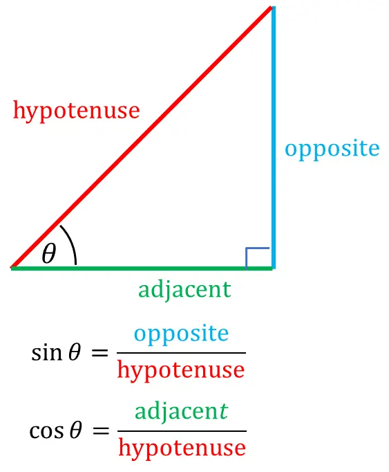
Figure (1): The theory of trigonometry
3- OBJECTIVE OF THE PROJECCT:
Designing a matlab program that plot and animate the movement of the two robotic arms and store it in an “.avi” format.
- For robotic arm_1 assuming the starting coordinates: X0=0; Y0=0; and ending coordinates is changing as θ1 changes as X1=L1*cos(θ1); Y1=L1*sin(θ1).
- For robotic arm_2 assuming the starting coordinates:X1=L1*cos(θ1); Y1=L1*sin(θ1); and ending coordinates is changing as θ2 changes as X2=X1+L2*cos(θ2); Y2=Y1+L2*sin(θ2). All this is demonstrated in figure (2).
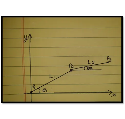
Figure (2): Demonstrated of the three points of the robotic arms.
4- BODY OF THE CONTENT:
The movements of the robotic arms can solved using a matlab program as follow:
%writting a program to simulate the forward kinematics of a 2r obotic arm
%using multiple values for theat1 and theat2, and using for loop
close all
clear all
clc
%define the inputs, assuming that x0 and y0 start at origin, and theta1,
%and theat2 each represent 10 values
L1=1;
L2=0.5;
x0=0;
y0=0;
theta1=linspace(0,90,10);
theta2=linspace(0,90,10);
%using for loop to simulate the forward kinematics of a 2r robotic arm to
%repeat the calculations for theta1 and theta2 ten times
%Length(theta1) means the number of valus in theta1
%using ct to increment
ct=1;
for i=1:length(theta1)
    THETA1=theta1(i);
    for j=1:length(theta2)
    THETA2=theta2(j);
% writing codes to calculate x1,y1,x2,y2 for both first and second arms,
% using theory of trigonometry: X=L*cosd(theta); Y=L*sind(theta)
x1=L1*cosd(THETA1);
y1=L1*sind(THETA1);
x2=x1+L2*cosd(THETA2);
y2=y1+L2*sind(THETA2);
% ploting the first, and second arms in the same plot, using linewidth 4
plot([x0 x1],[y0 y1],[x1 x2],[y1 y2],'Linewidth',4)
% setting the start and end for both x-axis, and y-axis
axis([-0.1 1.5 0 1.5])
% pausing the frames with 0.01s
pause(0.03)
% saving the animated plot into an array called K, where ct is represent a
% frame
M(ct)=getframe(gcf);
ct=ct+1;
    end
end

% generate a movie from all frames,and save it in AVI formate
movie(M)
% create AVI to dump out all frames, and gave it a file name and profile
videofile=VideoWriter("Forward Kinematic.avi","Uncompressed AVI")
% open the video file
open(videofile)
% write all the frames into the video
writeVideo(videofile,M)
% close video
close(videofile)
The algorithm that has been used in this program is "For Loop", which will repeat the command with specified number of times. The program starts by define the inputs, assuming that x0 and y0 start at origin, and theta1, and theat2 each represent 10 values here "linspace" code been used to generate the 10 values for each. As demonstrated in figure (2) the three points can be solved into:
P1=(X0,Y0)=(0,0),and P2=(X1,Y1) by using the trigonometry of the triangle, therefore; P2=(L1*cosθ1,L1*sindθ1), finally P3=(X2,Y2) can be represented as (X1+L2*cosθ2, X1+L2*sinθ2). So after defined the inputs the algorithm of the "for" has been used since having both θ1, and θ2 so the below "for" is used to change the values for both θ1, and θ2 into new varibles called θ_1, and θ_2 respectivily each ten times values. Therefore the first arm will shows 10 change in its value, while second arm will have also 10 times .
in this case the terms i, and j has been defined so now both but before that the code "ct" has been used to increment the number of times the program excute the command as shown bellow:

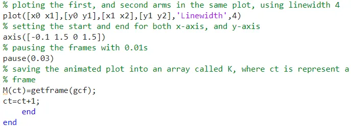
Then ploting the first, and second arms in the same plot, using linewidth 4, and setting the start and end for both x-axis, and y-axis, by using the "pause" command to pause each frames speed by 0.03 second is number is optional, and then adding the command "M(ct)=getframe(gcf)" to get the each frame and store them in an array called M, finally ading the increment by writhng the code "ct=ct+1" so everytime add one and finally closeing the by tyipng "end" two times as below.
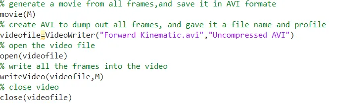
And finally writing the code to save the sotred array M as an animated movie from all frames, and save it in AVI formateby writing movie(M). And create AVI to dump out all frames, and gave it a file name and profile using the command to "videofile=VideoWriter("Forward Kinematic.avi","Uncompressed AVI")", then open the video file by typing "open(videofile)" and write all the frames into the video with code "writeVideo(videofile,M)" and finally closing the video file by writing "close(videofile)" as below:
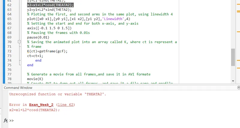
Errors While Programing:
Youtube Link: https://www.youtube.com/watch?v=lCm0YQnF-qk
G-Drive Link: https://drive.google.com/file/d/11AQfs0RzpJDuDKHKjmc0zRTMgnI8EuZk/view?usp=sharing
Simulation Project:
Designing a code to simulate the movement of the watch, using the same theory mentioned above, but this time the second arm assumed to be started at the origin (0,0), the output animation will be stored as "Design Watch.avi" the below is attched code with explinations.
%writting a program to simulate the movement of the watch
%using multiple values for theat1 and theat2, and using for loop
close all
clear all
clc
%define the inputs, assuming that x0 and y0 start at origin, and theta1,
%and theat2 each represent 10 values
L1=1;
L2=0.5;
x0=0;
y0=0;
theta1=linspace(0,360,10);
theta2=linspace(0,360,10);
%using for loop to simulate the movement of watch to repeat the calculations
% for theta1 and theta2 ten times
%Length(theta1) means the number of valus in theta1
%using ct to increment
ct=1;
for i=1:length(theta1)
    THETA1=theta1(i);
    for j=1:length(theta2)
    THETA2=theta2(j);
% writing codes to calculate x1,y1,x2,y2 for both first and second arms,
% using theory of trigonometry: X=L*cosd(theta); Y=L*sind(theta)
x1=L1*cosd(THETA1);
y1=L1*sind(THETA1);
x2=L2*cosd(THETA2);
y2=L2*sind(THETA2);
% ploting the first, and second arms in the same plot, using linewidth 4
figure(1)
plot([x0 x1],[y0 y1],[x0 x2],[y0 y2],'Linewidth',4)
% setting the start and end for both x-axis, and y-axis
axis([-1.5 1.5 -1.5 1.5])
grid on
% pausing the frames with 0.01s
pause(0.5)
% saving the animated plot into an array called K, where ct is represent a
% frame
M(ct)=getframe(gcf);
ct=ct+1;
    end
end

% generate a movie from all frames,and save it in AVI formate
movie(M)
% create AVI to dump out all frames, and gave it a file name and profile
videofile=VideoWriter("Design Watch.avi","Uncompressed AVI")
% open the video file
open(videofile)
% write all the frames into the video
writeVideo(videofile,M)
% close video
close(videofile)
Output:
Youtube Link:https://youtu.be/BxZJRNWXqQQ
5- CONCLUSION:
Using matlab to design and simulate the forward kinematics of a 2r obotic arm using multiple values for θ1 and V2, and using for loop to change the values for the both angles rather than using a single values for both angles. The movement of both arms also can be represent the movement of the watch's arms and that has been described with a matlab codes and the output has been saved as "Design Watch" in which the scond arm start coordinated assumed to be (0,0) and both x-axis, and y-axis changed form [(-1.5 1.5 -1.5 1.5]).