AIM:
Simulating Forward Kinematics of a 2R Robotic Arm using MATLAB program.
OBJECTIVES:
1. Write a program in Matlab to simulate the forward kinematics of a 2R Robotic Arm.
2. Creating an animation from the plots obtained in the program.
3. Understand the movement of an 2R Robotic in 2D workspace.
THEORY:
The robotic arm is a type of mechanical arm, usually programmable, with similar functions to a human arm; it may be the entire mechanism or part of a more complex robot. Joints allow rotation or translational motion between the links of such a manipulator. The manipulator can be regarded as a kinematic chain. It is analogous to the human hand, and is the end effector of the manipulator's kinematic chain. Using the kinematic equations of a robot, forward kinematics calculates the position of the end-effector based on specified values of joint parameters.
In forward kinematics, joint parameters are used to determine the position of an end-effector by using the kinematic equations of a robot. The robotic arms are used in a variety of industrial applications, such as drilling, welding, metal cutting, and painting.
Here we have a 2R Robotic arm as shown in the figure: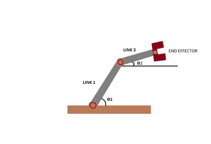
*Link-1 is connected to the base, and the end of link-1 is connected to link-2. The end of link-2 is connected to the end effector that performs the desired operation. We will restrict the movement of the links in this project to a 2D plane
RESULT:
% A program to simulate the forward kinematics of a 2R Robotic Arm
clear all
close all
clc
% Taking inputs
% Length of link-1 (L1) and link-2 (L2) in meter
L1=1;
L2=0.5;
% Angle traced by link-1 in degrees (theta_1)
theta_1=linspace(0,90,10);
% Angle traced by link-2 in degrees (theta_2)
theta_2=linspace(0,90,10);
% Initialising base coordinates of link-1
x_0=0;
y_0=0;
ct=1;
for i=1:length(theta_1)
THETA_1 = theta_1(i);
%taking particular values of angle traced by link-1 in order.
for j = 1:length(theta_2)
% Iterating all values of theta_2 for particular value of theta_1
THETA_2=theta_2(j);
%taking particular values of angle traced by link-2 in order.
% Calculating the coordinates of end point of link-1
x_1=x_0+L1*cosd(THETA_1);
y_1=y_0+L1*sind(THETA_1);
% Calculating the coordinates of the end of link-2
% End coordinates for link-1 are the start coordinates for link-2
x_2=x_1+L2*cosd(THETA_2);
y_2=y_1+L2*sind(THETA_2);
% Plotting the robotic arm for simulation
plot([x_0 x_1],[y_0 y_1],[x_1 x_2],[y_1 y_2], "linewidth",2);
axis([-0.1 1.5 0 1.5]);
% Pausing the current plot for a while before movoing to the next
% plot
pause(0.1);
% Capturing the current plot to combine later
M(ct) = getframe(gcf);
% Incrementing ct so that each frame is captured in M
ct=ct+1;
end
end
% Making a movie from collected frames
movie(M);
% Creating a video file of '.avi' format to save the animation
videofile=VideoWriter('forward_kinematics_of_2R_robotic_arm.avi','Uncompressed AVI');
open(videofile);
% Writing the movie in the videofile created
writeVideo(videofile, M);
close(videofile);
EXPLANATION OF THE PROGRAM:
1. The lengths of both links are used as input. Length of link-1 (L1) is taken as 1m and length of link-2 (L2) is taken as 0.5m.
2. Angles traced by both links are taken as input for link-1 and link-2. Angles are varied over a range to simulate the movement of the robotic arm.
3. Base position of link_1 (x0,y0) is considered as origin(0,0).
4. In order to iterate over the range of angles traced by both links, two for loops are used. In order to obtain different positions of the end effector at each angle of link-1, link-2 is moved over its entire range in response to that angle.
5. For a particular value of Θ1 and Θ2, the end position of link-1 is calculated by these equations.
x1 = x0 + L1.cos(Θ1)
y1 = y0 + L1.sin(Θ1)
The end position of link-1 is also the start position of link two. The end position for link-2 is calculated by these equation.
x2 = x1 + L1.cos(Θ2)
y1 = y1 + L1.sin(Θ2)
6. After each position of link-1 and link-2 is determined, a plot is created, which is then captured frame by frame to make a movie.
7. To save the movie, a video file of '.avi' format is created.
8. As a result, the final animation is created by writing the movie into the video file.
OUTPUT: An animated video clip is obtained as the output. To view this animation, follow the link provided below.
CONCLUSION:
A simulation of the forward kinematics of a 2R Robotic Arm was created using the MATLAB program.