Week 2- 2R Robotic Arm Challenge
AIM:
To simulate the forward kinematics of a 2R Robotic arm using MATLAB Program.
Introduction:
In the robotic field of kinematics, the robot is an essential part by which we can program & simulate how a robot will move. by simulation, we can figure out the workspace of the robot for design.
In Industries like automobiles, aviation the manufacturing layout are designed with automation for doing matching, assembly & painting. so using MATLAB Software we can calibrate the work space & robotic arm movements etc.
GOVERNING EQUATION:
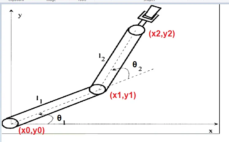
The equation for calculating coordinates of link starting & ending points.
As per the image we are considering l1 = 100mm & l2 = 50mm length arm with respect to horizontal axis respectively.
coordinates of Link1:
starting point = [X0,Y0] = [0,0]
Ending point = [X1,Y1] = [`l1cosd theta_1,l1sind theta_1`]
coordinates of link2:
starting point = [X1,Y1] = [`l1cosd theta_1,l1sind theta_1`]
Ending point = [X2,Y2] = [`l2cosd theta_2,l2sind theta_2`]
Objective:
We will take multiple values of θ1 range of 0 to 120 degree & θ2 range of 0 to 90 degree the value of the arm movement is plotted. noting the values of the coordinates.
By the end examining the animation we are able to study the workspace motion involved in the cycle of the robotic arm.
Program:
clear all
close all
clc

% input
l1 = 100;
l2 = 30;
theta1 = linspace(0,120,10);
theta2 = linspace(0,90,6);

loop_counter = 1;

for i = 1:length(theta1)
    THETA1 = theta1(i)

for j = 1:length(theta2)
    THETA2 = theta2(j)
    x0 = 0
    y0 = 0

    x1 = l1*cosd(THETA1)
    y1 = l2*sind(THETA1)

    x2 = x1 + l2*cosd(THETA2)
    y2 = y1 + l2*sind(THETA2)

    %PLOTTING

    plot([x0 x1],[y0 y1],[x1 x2],[y1 y2],'linewidth',3)
    axis([-65 130 0 130])

    title('Kinematics of 2R Robotic arm')

    xlabel('arm movement in x-axis');

    ylabel('arm movement in y-axis');
    grid on
    pause(0.7)

    m(loop_counter) = getframe(gcf)
    loop_counter = loop_counter+1

end
end

movie(m)
videofile = VideoWriter('arm_movement.mp4','Uncompressed AVI');
open(videofile)
writeVideo(videofile,m)
close(videofile)
l1 is the length of link 1
l2 is the length of link 2
theta 1 represents the 10 values ranging from 0 to 120 degree using linspace command
theta 2 represents the 6 values ranging from 0 to 90 degree using linspace command
; is used to avoid printing the values in command window.
ct = 1indicates the loop execution.
THETA1 is a variable (contains one variable) but theta1(i) is an array (contains 10 values). i represents the loop count
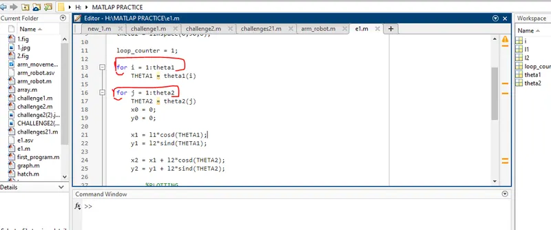
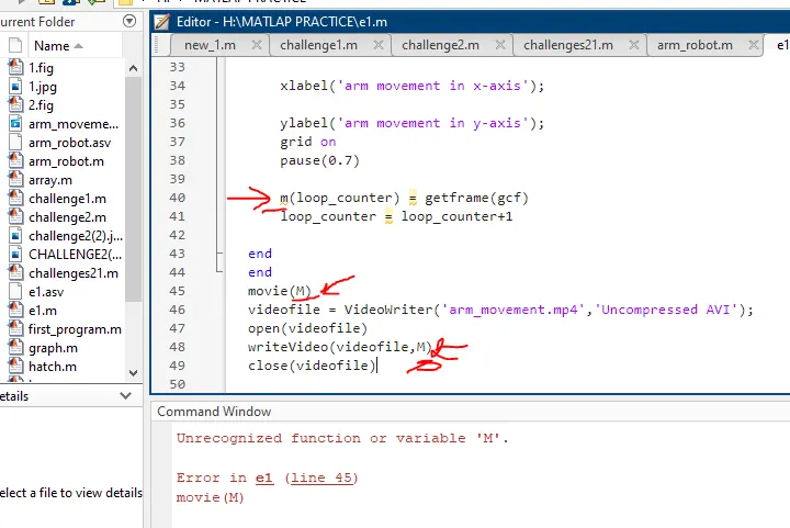
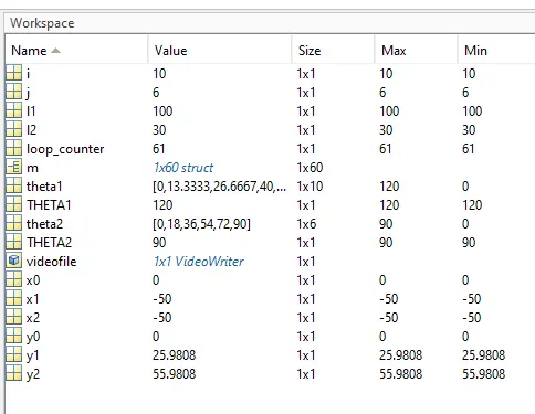
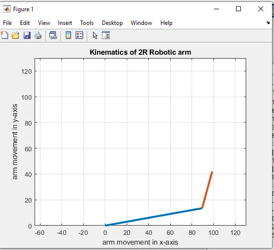
- After generating animation by examining closely we can understand the workspace of the Robotic arm.
- By changing the length & angle of the robotic arm we can exactly know the position at a different angle.