Week -2
AIM:
.to make a simulink model of doorbell using solenoid block
.to use a thermistor to sense the temperature of a heater and turn off the fan according to temperature
Q1 . make a simulink model of the doorbell using a solenoid block with the following details
SOLUTION :
THEORY
1. the circuit of the door bell using a solenoid block is as shown in fig
2.when we close the switch we complete the circuit then the electric current is flown through the circuit
3.after that the electromagnet gets charged and then it acts like a magnet due to which it pulls the nears metal clip towards it
4. as the metal clip moves towards the magnet ,the extended part of the metal clip hits the gong and creates the sound
5. which we refer to as the sound of the bell
. following is the simulation model for the door bell using a solenoid block
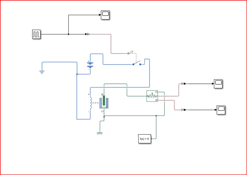
. in the above model the simulation blocks used and their purpose are as follows
1.pulse generator: the pulse generator block generates square wave pulse at regular intervals .the block waveform parameters , amplitude ,pulse width ,period and phase delay,fetermine the shape of the output waveform
2.scope: display signals generated during simulation
3. simulink-ps-coverter: converts the simulink input signal to a physical signal
4.spst switch: the block represents a single- pole single-throw switch controlled by an external control vt. if vt is greater than the threshold ,then the switch is closed ,otherwise ,the switch is open
5. battery: it is a stored electrical source for the electrical circuit
6. electrical reference: the electrical reference block represents an electrical ground
7. solenoid: the solenoid block represents the electrical charactristics and generated force for the solenoid . this solenoid block represents port r moves towards part c
8. mechanical translation reference: the mechanical translational reference block represents a reference point ,or frame for all mechanical translational ports
9.solver configration : the solver configration block specifices the solver parameters that yours model needs before you can begin the simulation
10. ideal motion translation sensor: it acts as a motion sensor in mechanical translational systems the ideal translational motion sensor block represents a device that converts an across variable measured between two mechanical translation nodes into a control signal proportional to velocity or position . you can specify the intial position as a block parameter
11. ps -simulink converter : converts the input physical signal to a simulink output signal
WORKING OF MODEL:
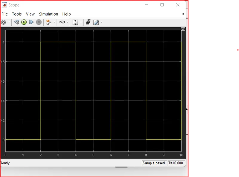
1.pulse generator creates an input signal of pulse with 1 unit amplitude ,4 sec peroid ,having 50% pulse width with 2sec delay for the model
2. then we attach the scope to it get so that we can compare the inputs and outputs of the model
3.now the input signal is connected to the simulink -ps converter which converts the simulink signal to a physical signal which is then sent towards the spst switch
4. after receiving the physical signall , the spst switch compares it with its threshold value if it's greater than it, then it closes the electric circuit ,or else it is open
5. after the electric circuit is closed the current is flown from the circuit and then it energies the solenoid connected to the battery
6. as the solenoid is charged it pulls the part r towards port c
7. a mechanical translation reference is attached to the port r of the solenoid to understand the position and velocity of the plunger of the solenoid
8. to record its position and velocity ps-converter converts the physical signal to a simulink signal and then using scope block we record it for the simulation duration
RESULTS:
.PULSE VALUE VS TIME
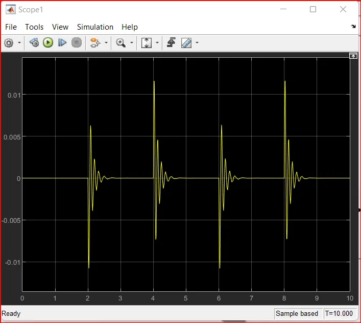
.POSITION VS TIME
VELOCITY VS TIME
Q2. use a thermistor to sense the temperature of a heater and turn on or turn off the fan as per the below conditions
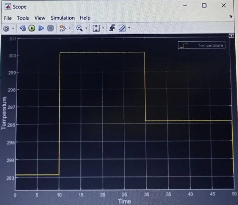
. temperature source :20c from 0 to 10seconds ,27c from 10 to 30 seconds ,23c from 30to 50second.
. fan conditions : on if the temperature above 25c ,off otherwise
.SOLUTION:2
THEORY
. a thermistor is a type of resistor whose resistence is strongly dependent on temperature , more so than in standard resistors .the word is a combination of thermal and resistor .thermistor are widely used as inrush current limiters ,temperaature sensors ,self-resetting overcurrent protectors and self-regulating heating elements
. thermistors are of two opposite fundamental types:
1. with ntc thermistors ,resistance decrease as temperature rises usually due to an increase in conduction electrons bumped up by thermal agitation from the valency band an ntc is commonly used as a temperature sensor ,or in series with a circuit as an inrush current limiter
2. with ptc thermistor , resistance increase as temperature rises usually due to increased thermal lattice agitations particularly those of impurities and imperfections ptc thermistors are commonly installed in series with a circuit and used to protect against overcurrent conditions as resettable fuses
.FOLLOWING IS THE SIMULATION MODEL FOR USING A THERMISTOR TO SENSE THE TEMPERATURE OF A HEATER AND TURN ON OR TURN OFF THE FAN AS PER CONDITIONS
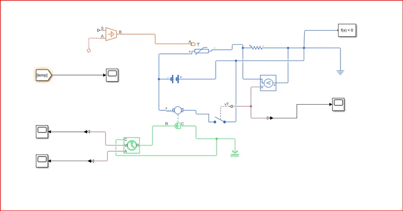
in the above model the simulation blocks used and their purpose are as follows
1. controlled temperature source - the controlled temperature source block represents an ideal source of thermal energy that is powerful enough to maintain specified temperature difference across the source regarding of the heat flow consumed by the system
2. thermistor- the thermistor block represents an ntc thermistor using the b- parameters equation the resistance at temperature t is R=R0.e6N(1/T1-1/T0)
3.resistor - the resistor block represents a linear resistor
4. voltage sensor - the voltage sensor block represents an ideal voltage sensor,that is a device that converts voltage measured between two points of an electric circuit into a physical signal proportional to the voltage
5. spst switch- the block represents a single -pole single -throw switch controlled by an external control signal vt .if vt is greater than the threshold ,then the switch is closed ,otherwise ,the switch is open
6. battery- the battery block represents a simple battery model
7. electric reference- the electric reference block represents an electrical ground
8.universal motor- the universal motor block represents the electrical and torque characteristics of a universal motor
9. mechanical rotational reference- the mechanical rotational reference block represents a reference point ,or frame,for all mechanical rotaional parts
10. ideal rotaional motion sensor- the ideal rotational morion sensor block represents an ideal rotational motin sensor ,that is a device that converts an across variable measured between two mechanical rotational nodes into a signal proportional to angular velocity or angle
11. solver configuration- the solver configuration block specifies the solver parameters that your model needs before you can begin the simulation
12. ps-simulink converter- converts the input physical signal to a simulink output signal
13. scope- display signals generated using simulation
14. from- the form block accepts a signal from a corresponding goto block then press it as output the data type of the output is the same as that of the input from the goto block from and goto block allows you to pass a signal from one block to another without actually connecting them
15. temperature source is the subsystem block which is as follows
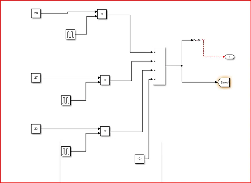
1.constant- the constant block generates a real or complex constant value signal
2.pulse generator- the pulse generator block generates square wave pulses at a regular intervals .the block waveform parameters ,amplitude ,pulse width,period,and phase delay, determine the shape of the output waveformm
3. product- the product block outputs the result of multiplying two inputs ;two inputs ;two scalars ,a scalar and a nonscalar ,or two nonscalar that have the same dimensions
4. add- the sum block performs addition or suntraction on its inputs
5.scope- display signals generated during simulation
6. goto-the goto block passes its input to its corres[onding from blocks the input can be a real-or complex -valued signal or vector of any data type .from and goto blocks allow you to pass a signal from one block to another without actually connecting them
7. simulink-ps converter- converts the simulink input signal to a physical signal
8. thermal input- it is an output of this subsystem tht is connected to the controlled temperature source in the main model
.WORKING OF SUBSYSTEM MODEL:
1. according to the given conditions we need to build the temperature source 20c from 0 to 10second,27c from 10to 30seconds, 23c from 30to 50seconds
2. so we use the constant block to provide three constant temperature then we need to specify its duration so we can create the pulse block to provide which has 1 unit amplitude 50sec peroid 20% &40% pulse widthj and with 0 sec .10sec,30sec delay for respective pulse generator
3 then we take the products of constants and their respective pulse generator
4. by adding them we can create the signal needed according to the given conditions
5. add we add another constant value 273.15 ,which converts deg celsius value to deg kelvin
6.futher a 'goto' block is connected to the add block which transfers the same signal to the 'from' block
7. the signal from the 'add' block is connected to the simulink -ps converter and then it is further sent as the output signal of this subsystem model
WORKING OF THE MODEL
1. the temperature source subsystem model provides the temperature to the controlled temperature source according to the inputs it provides the surroundings temperature condition to the therostart
2. the thermosart is connected in a closed circuit with a battery and a resistor connected in a series combination with it
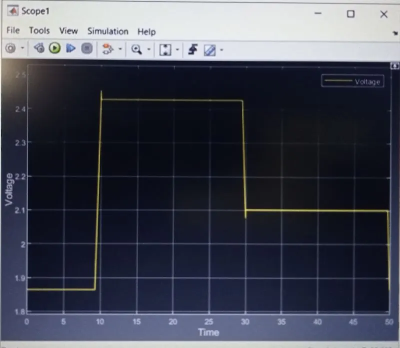
3 as the temperature increases the thermostat resistance value decreases and the overall current in the circuit increases which leads to an increase in the voltage sround the resistor of 10ohms
4. we note the voltage around the resistor when the temperature is about 25deg celsius which is 2.273v
5.by using the ps-simulink converter we convert a physical signal from the voltage sensor into a simulink signal and record it using a scope block to understand how voltage varies with temperature
6. the voltage sensor signal is also sent spst whose threshold value is 2.273v.
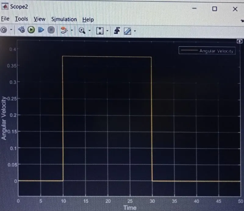
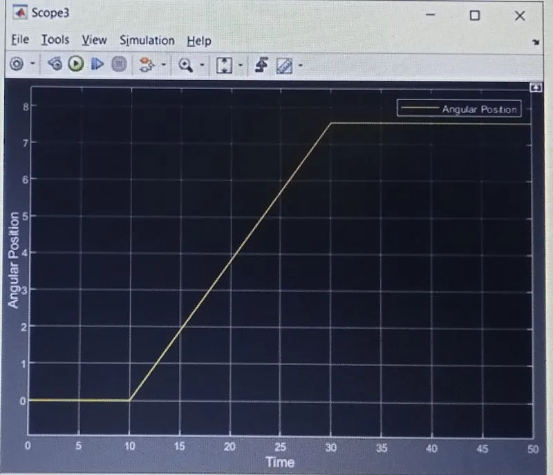
7. as the universal motor is connected in series with spst switch and to the battery ,it gets on only when the temperature is adove 25deg celsius
8. to verify the outcome of the universal motor we have attached the ideal rotational motion sensor to it
9. now the ps-simulink coverter the physical signal from the rotational sensor and converts it into a simulink signal which is then used to record the angular velocity and angle of the universal motor
RESULTS:
. temperature vs time
. voltage vs time (voltage of resistor)
. angular velocity vs time
. angular position vs time
CONCLUSION:
. we have completed and run the model of the doorbell using a solenoid block
. thus bell is rung for every alternate 2 seconds
. we have completed and run the model of using a thermistor to sense the temperature of a heater and turn on or turn off the fan as per conditions
. thus fan is turned on only when the temperature is above 25 deg celsius
. we observe the little spike in voltage vs time plot of the resistor ,its because we use the same battery source for the motor also since the motor is turned on and off anly when the temperature is above or below 25 deg celsius respectively these spikes can only observe during that change