Week -2
Answer-1
Aim-Make a Simulink model of Doorbell using solenoid block.
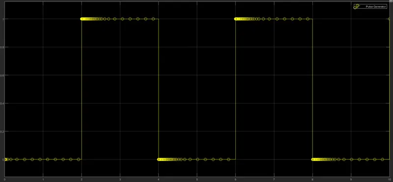
Create a situation where the switch is closed for 2 seconds and then released. Observe the physical movement of the plunger.
Theory-
Doorbell- It is a device which uses electrical and mechanical components to produce sound when the switch is pressed.
when the switch is closed the electromagnet receives electrical power from the battery and pulls the metal arm to hit the bell which produces sound.
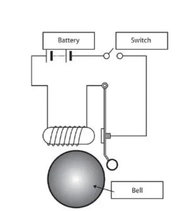
The solenoid is an electromagnet with wire winding and a small metal piston inside it, when electric current flows through the wire an electromagnetic field is generated which pulls the metal piston towards it. The metal piston hits the bell.
Blocks Used-
pulse generator: The Pulse Generator block generates square wave pulses at regular intervals. The block waveform parameters, Amplitude, Pulse Width, Period, and Phase delay, determine the shape of the output waveform.
Simulink-PS Converter: It Converts the Simulink input signal into a physical signal.
Scope: It displays signals generated during simulation.
Switch: Switch controlled by an external physical signal.
Battery: It gives the power to the close loop.
Electrical reference: It shows Connection to electrical ground.
Solenoid: Electrical characteristics and generated force of solenoid.
Ideal translational Motion Sensor: It is a motion sensor in mechanical translational systems.
Mechanical Translational References: Reference connection for mechanical translational ports.
PS-Simulink Converter:It Converts physical signal into Simulink output signal.
Display- to display the values of i/p and o/p.
Solaver Configuration-It specifies the solver parameters that a model needs before you begin the simulation.
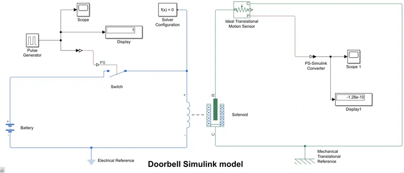
simulink model file attached named as doorbell.
Output Waveform of Pulse Geanerator-
Main Output Waveform -
at spring constant=400 N/m
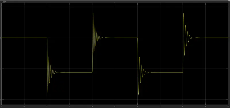
Result-
when the switch is closed for 2 seconds and then released we observed the physical movement of the plunger by ideal translational motion sensor which hits the bell for 2 seconds and then stops.
-------------------------------------------------------------------------------------------------------------------------------------
Answer-2
Aim- Use a thermistor to sense the temperature of a heater & turn on or turn off the fan.
conditions: Temperature source: 20 °C from 0 to 10 seconds, 27 °C from 10 to 30 seconds, 23 °C from 30 to 50 seconds
Fan conditions: ON if the temperature above 25 °C, OFF otherwise.
Theory-
Thermistor- it is a thermal resistor whose electrical resistance value varies when the temperature changes.
Types-
1. Negative temperature coefficient (NTC)- when temperature increases resistance value will decrease.
2. Positive temperature coefficient (PTC)- when temperature increases resistance value will increase.
Blocks Used for modelling-
Signal Builder- to build the signal as required
Display- shows the input and output values
Scope- for showing waveforms and graphs
Simulink-PS Converter- to convert simulink signal into physical signal
Controlled Temperature Source- gives controlled temperature to thermistor
Thermistor- used a NTC thermistor which decrease its resistance when temp increases
12V Battery- power supply for the circuit
Resistor- it apposes the flow of current
Volatage Sensor- to sense the voltage across resistor
PS-Simulink Converter- to convert physical signal into simulink signal
Switch- Voltage is given to it by voltage sensor and we have used two constants i.e. 0 and 1.
Constant- to give constant values
Solver Coniguration- The Solver Configuration block specifies the solver parameters that the model needs before the begining of simulation
Controlled Voltage source- converts a Simulink input signal into an equivalent voltage source
DC motor- used to run the fan.
Ideal rotational motion sensor- to sense that the fan is running or not
Mechanical rotational reference- to connect mechanical rotational ports that are rigidly affixed to the frame (ground).
Electrical reference- it represents an electrical ground
Simulink Model:
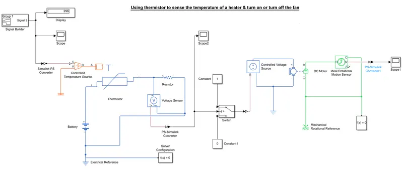
*Simulink Model file attached named as Thermistor.
In this model we have used a signal builder to build a signal as required, in this signal builder the temperature values used are kelvin like 293 for 20 degree, 300 for 27 degree, 296 kelvin for 23 degree.
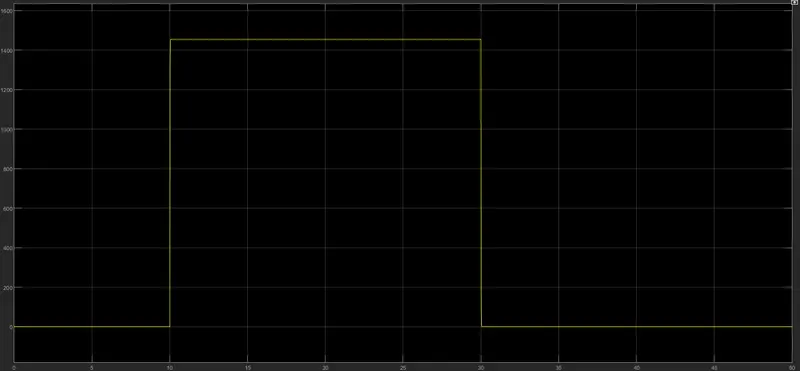
We have used a DC motor here because fan is runs by a motor and then we have sensed it rotation by ideal rotational motion sensor that shows that the fan is running after 25 degree temperature.
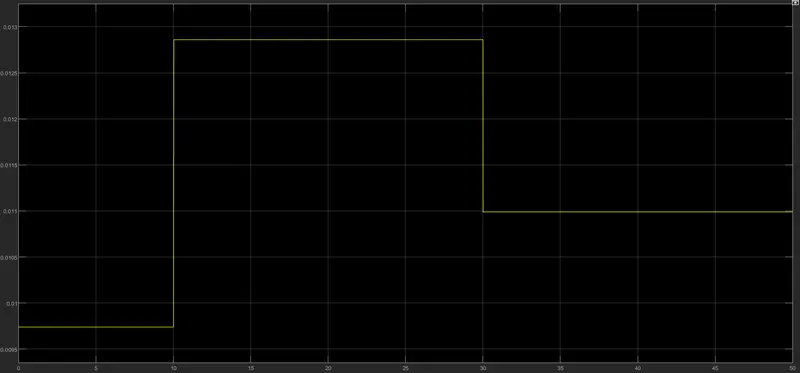
Output Signal of Voltage sensor:
Output Signal of Ideal Rotational motion sensor:
Result-
- when the temperature is under 25 degrees like 20 and 23degree the DC motor isn't running that means the fan is not running.
- When the temperature value crosses the 25 degree i.e. 27 degree the DC motar starts to run and hence by ideal rotational motion sensor it is observed that the fan is running at 27 degree temperature.
- It is observed that below 25 degree temp the fan is not running and hence all the conditions are satisfied.