Week -2
1) Door Bell
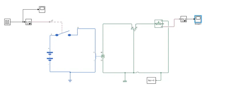
The Above simulink model realises the working of a Door Bell using solenoid block.
In the above model we use
- SPST Switch : Single pole single throw switch, which is used only to ON and OFF the circuit
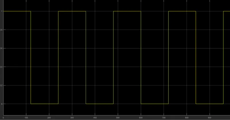
- Pulse generator : For providing pulse to regulate the switch having a time period of 240 sec
- Solenoid : It is a electro magnetic device which produces a uniform magnetic field. Force of the magnetic field is determined by number of turns or the current passing through the coil. In this simscape model Plunger is initially at position X, When the inductor part is charged, Magnetic fileld is produced and Plunger moves. A damper and Spring is attached in this model to have a desired behaviour.
- Lever: Here lever is used as a replacement to metal arm.
- Translational Motion Sensor: This sensor is responsible for detecting a physical movement in the system and measure the change
Input Signal
Output Signal Measured
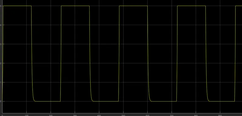
From the above measured value, we could observe that Whenever the circuit is on by providing a pulse, there is a movement in Solenoid which causes a physical displacement in Lever attached.
2)
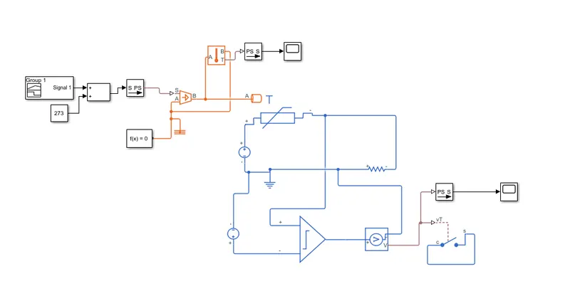
The above model is a realisation of thermister used to control fan switch as per the temp conditions given above
Signal Builder block: This block is used to produce user defined signals. Please refer input signal image for further details
Controlled Thermal Source: The block takes in a Physical signal for Maintaining the heatflow as reqiuired. Heat flow at port B is determined by difference of Physicl signal and Thermal reference A.
Temperature Sensor: Used to measure temp at Source.
Thermister: The block represents a NTC Thermister, This is a temp sensor where change in temp is observed in change in resistance across. In our case Resistance of the Thermister is reduced when change in temp is positive.
Comaparator: This is a integrated circuit used here to filter out temp values less than 25 degC. Reference is set as Voltage corresponding to 25 degC(298.15K).
Voltage Sensor: This block takes in Voltage value from circuit and converts it to physical Signal.This Physical Signal is used to control the SPST switch(Fan Switch).
Input Signal
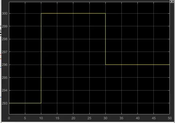
For First 0-10 sec, temp is 293K,
10 - 30 sec, temp is 300K &
30 - 50 sec , temp is 296K
Output
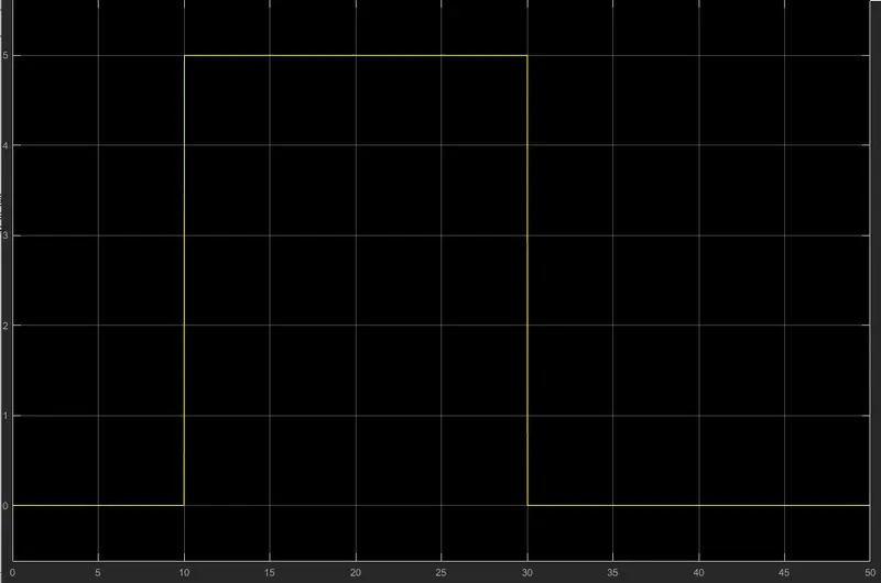
10 to 30 Sec, The switch for the fan is ON
From Output signal we can verify that Fan is ON only When Temp is greater than 25 degC (298.15 K)