Week -2
ANSWER 1:
Things we need to know for this simulation is as follows:
- Solenoid: In short, we can say the solenoid is the iron coil through which electric current is passed and it acts as a magnet. Its conventional flow of current can be understood with the help of the right hand thumb rule.
- Simulink - PS converter: Converts the simulink input signal into physical signal. Here in input we can pass signals as well as the first derivatives as well as second derivatives. The unit expression in input signal unit parameter is associated with the Simulink input signal and determines the unit assigned to the physical signal.
- PS - Simulink converter: Converts the input physical signal into Simulink output signal. The unit expression in the ‘output signal unit’ parameter must watch the unit of physical signal and determine the conversion from the Physical signal to the Simulink output signal.
- Ideal Translational Motion Sensor: The Ideal Translational Motion Sensor block represents a device that converts an across variable measured between two mechanical translational nodes into a control signal proportional to velocity or position. You can specify the initial position (offset) as a block parameter.The sensor is ideal since it does not account for inertia, friction, delays, energy consumption, and so on. Connections R and C are mechanical translational conserving ports that connect the block to the nodes whose motion is being monitored.
- Solver Configuration: Each physical network represented by a connected Simscape block diagram requires solver settings information for simulation. The Solver Configuration block specifies the solver parameters that your model needs before you can begin simulation.
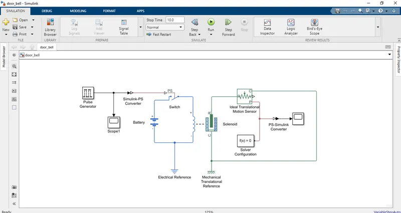
THEORY EXPLANATION: Here, in practical there is a simple mechanism of door bell is there is a iron coil and when the switch is made ON, there is a battery connected in this circuit along with the iron coil and as the circuit completes, a current passes through that iron coil and it acts as a magnet which makes that iron plunger to attract to it and due to that the plunger extension hits with the metal disc which we call bell and it rings. Now, as the plunger gets attracted, again the circuit is incomplete and the iron coil (solenoid) loses its magnetism and becomes a simple iron coil so that plunger again is in the normal position which makes the circuit complete which makes this same process to be repeated again. Thus, the bell rings until the switch is OFF.
PROCEDURE:
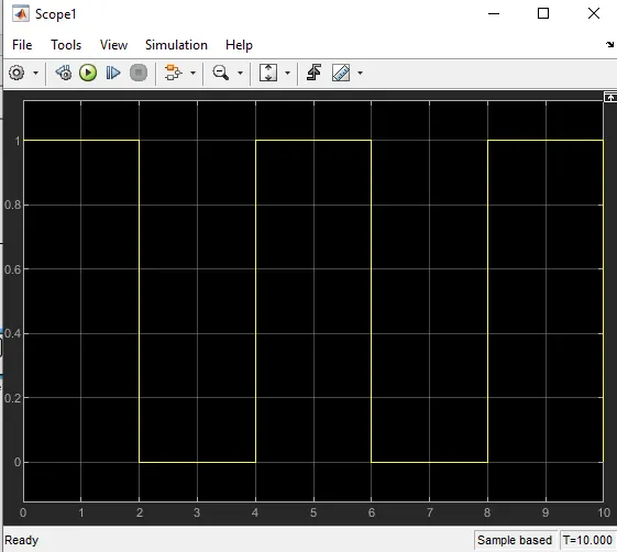
- Firstly in Pulse generator, we pass the input signal (wave) with parameters like Period of 4 seconds and pulse width of 2 seconds which is shown here below:
- With the help of simulink - PS converter that input is given to the switch which is connected to the battery and solenoid. So, the current is generated.
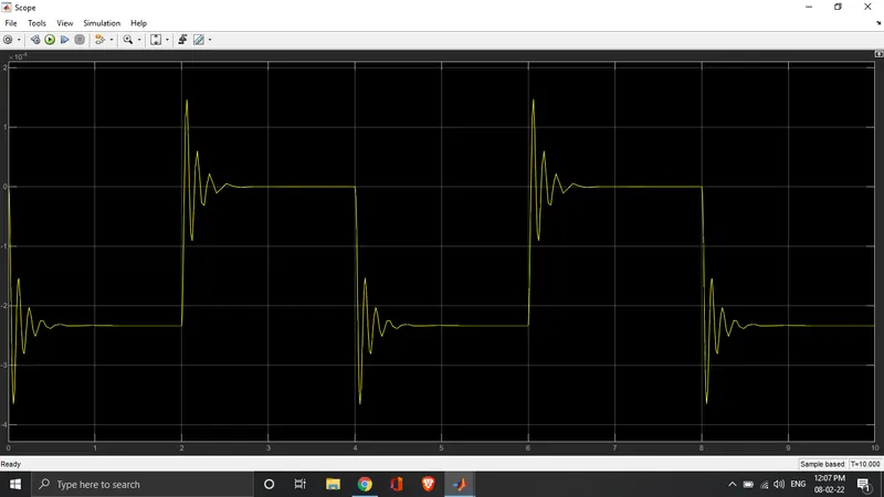
- The ideal translational motion sensor is connected which is used to understand the motion of the plunger and that also we can see in below given graph:
- Solver is used to understand the type of the system and solve accordingly.
- We can see different output by changing the parameters like spring constant, stroke, damping, etc in the mechanical section of the solenoid block.
Finally, we get to know the total system with the help of the block aggregated system in simulink.
ANSWER 2:
Things we need to know for this simulation is as follows:
- Signal Builder Block: The Signal Builder block allows you to create interchangeable groups of piecewise linear signal sources and use them in a model. You can quickly switch the signal groups into and out of a model to facilitate testing. In the Signal Builder window, create signals and define the output waveforms.
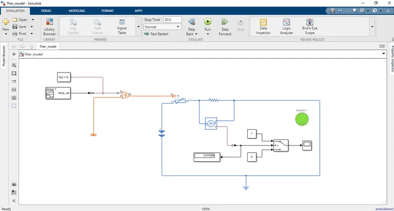
- Controlled Temperature Source:It represents an ideal source of thermal energy that is powerful enough to maintain specified temperature difference across the source regardless of the heat flow consumed by the system. Connections A and B are thermal conserving ports corresponding to the source inlet and outlet, respectively and port S is a physical signal port, through which the control signal that drives the source is applied.
- Thermistor: Thermistors are thermally sensitive resistors whose prime function is to exhibit a large, predictable and precise change in electrical resistance when subjected to a corresponding change in body temperature.This block represents an NTC thermistor using the B-parameter equation. The resistance at temperature T is
R=R0*e^B((1/T−1/T0))
Where:
- R0 is the nominal resistance at the reference temperature T0.
- B is the characteristic temperature constant.
- Voltage Sensor: The Voltage Sensor block represents an ideal voltage sensor, that is, a device that converts voltage measured between two points of an electrical circuit into a physical signal proportional to the voltage.Connections + and – are electrical conserving ports through which the sensor is connected to the circuit. Connection V is a physical signal port that outputs the measurement result.
- Switch Block: This block passes through the first input or the third input signal based on the value of the second input. The first and third inputs are data input. The second input is a control input. Specify the condition under which the block passes the first input by using the Criteria for passing first input and Threshold parameters.
PROCEDURE:
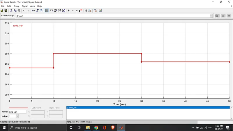
- Firstly, the input is passed through the signal builder block in which we can make the signals as per our need. so , we have modified the signal as per our the question shown below:
0 - 10 Sec → 293 k
10 - 30 Sec → 300 k
30 - 50 Sec → 296 k
- Passing that input via Simulink - PS converter to Controlled Temperature Source so that there is potential difference between the thermal reference and the input given to the thermistor.
- Battery is connected to pass the current inside the circuit.
- The thermistor is connected to a resistor and a voltage source which measures the threshold value required for our circuit to work and also keep the variable priority low otherwise there might be warning generated.
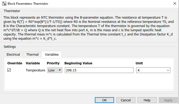
- Finally, it is passed to the switch which automatically does ON - OFF as the temp goes above and below 298K temperature.
- Lamp is connected to the switch so it lights when the switch is ON.
- Scope and Display blocks are used so their output can be seen below:
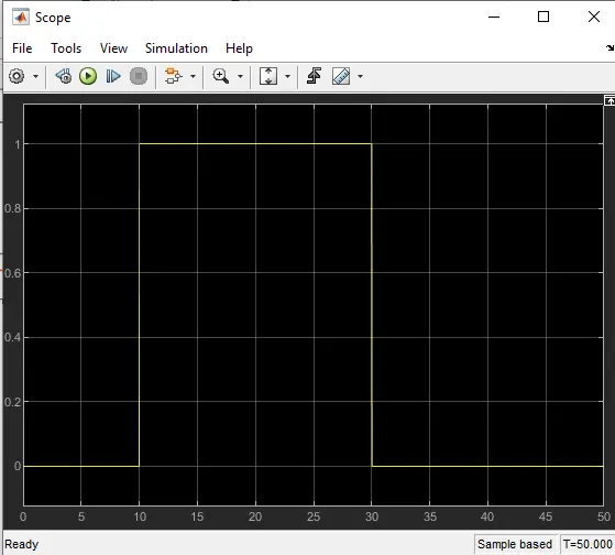
Finally, our aim got completed with the help of a thermistor and using different blocks in association with it in Simulink.