Week -2
SIMULINK MODEL OF A DOORBELL USING SOLENOID BLOCK AND CONTROLLING THE TEMPERATURE OF A HEATER USING A THERMISTOR
1.AIM
Make a Simulink model of Doorbell using Solenoid block with the following details:
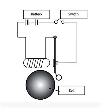
In the above arrangement, when the switch is closed the electromagnet receives electrical power from the battery and pulls the metal arm to hit the bell producing sound.
Create a situation where the switch is closed for 2 seconds and then released. Observe the physical movement of the plunger.
Assume remaining parameters.
BLOCKS USED IN MODEL
- Pulse Generator
- Switch
- Battery
- Solver configuration
- Solenoid
- Ideal translational motion sensor
- Mechanical translational reference
- Electrical reference
- Scope
SIMULINK MODEL
MODEL EXPLANATION
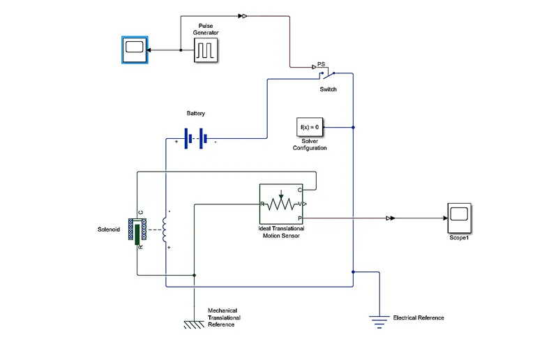
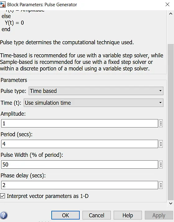
- The pulse generator is used to create square wave pulses at regular intervals.The block waveform parameters Amplitude,pulse width,period and phase delay,determine the shape of the output waveform.
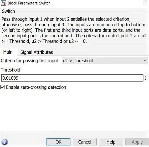
- The switch block is controlled by the external physical signal.If the external signal is greater than the thersold parameter then the switch is closed,otherwise switch is open.
- The Positive terminal of the battery is connected to switch and the negative terminal is connected to the electrical reference.
- The Solenoid block is connected with switch and battery and gets a complete electrical circuit.The C port is connected with mechanical reference.
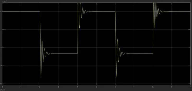
- The ideal translational sensor is connected with solenoid block R to observe the movement of the plunger.
- Scope is connected with the ideal translational sensor to get the output.
- PS-Simulink converter is used to convert the physical signal to simulink signal.
- Solver Configuration:Each Physical network represented by a connected simscape blocks requires solver setting information for simulation.
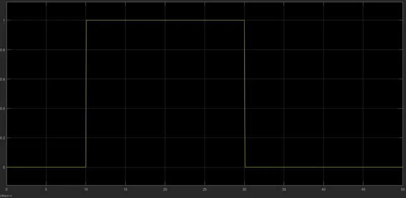
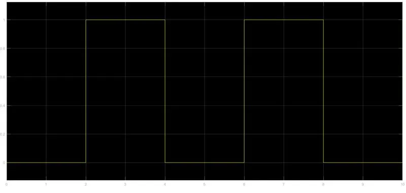
- Before we begin the simulation we need to setup an input parameter here in pulse generator where we delay time should be 2 seconds with amplitude 1 and pulse time should be 4 seconds to make it in half with 50% pulse width.
OUTPUT
The input signal of the pulse generator :
2.AIM
Use a thermistor to sense the temperature of a heater & turn on or turn off the fan as per the below conditions:
Temperature source: 20 °C from 0 to 10 seconds, 27 °C from 10 to 30 seconds, 23 °C from 30 to 50 seconds
Fan conditions: ON if the temperature above 25 °C, OFF otherwise
BLOCKS USED IN THIS MODEL
- Repeating sequence stair
- Controlled temperature source
- Thermistor
- Thermal Reference
- Resistor
- Voltage Sensor
- Battery
- Switch
- Electrical Reference
- Scope
- Display
- PS-Simulink converter
- Simulink-PS converter
- Solver Configuration
SIMULINK MODEL
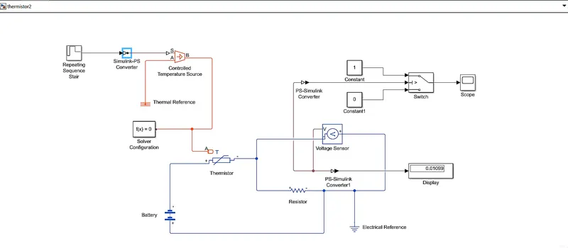
SIMULINK MODEL EXPLANATION
- Repeating sequence stair block is used to give the input values as per given conditions
At Point 1,Time = 0 seconds,Temperature = 293K
At Point 2,Time = 10 seconds,Temperature = 293K
At Point 3,Time = 10 seconds,Temperature = 300K
At Point 4,Time = 30 seconds,Temperature = 300K
At Point 5,Time = 30 seconds,Temperature = 296K
At Point 6,Time = 50 seconds,Temperature = 296K - Thermistor is known as Thermal Resistor which is defined as a type of resistor whose electrical resistance varies with changes in temperature.
- Although all resistor's resistance will fluctuate slightly with temperature, a thermistor is particularly sensitive to temperature changes.
- Thermistors act as a passive component in a circuit.They are accurate,cheap and robust way to measure the temperature.
- While thermistors do not work well in extremely hot or cold temperatures, they are the sensor of choice for many different applications.
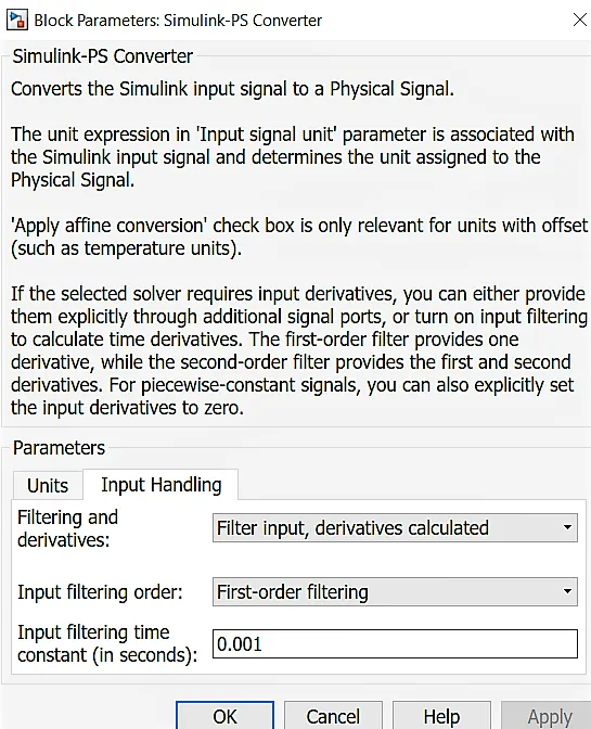
- we need to provide an integrated input in the simulink-PS converter block to be able to read the system.
- A linear Resistor is used in order to control the amount of current flowing from the battery.
- The voltage sensor is used to convert the voltage measured between two points into a physical signal.
- Solver Configuration:Each Physical network represented by a connected simscape blocks requires solver setting information for simulation.
OUTPUT