Week -2
problem statement 1
:-Make a Simulink model of Doorbell using solenoid block with the following details
answer :-
for making model of door bell with switch operated with delay of 2 sec as per requirement
- so for solving this we need:-
1.solenoid as doorbell is solenoid operated
2.switch
3.battery
4.pulse generator
5.display for result
6.scope for record result
7.electrical reference
8.mechanical reference
9.signal converter
- so basically we need take firstly to take battery source for opeartion of all our circuit
- after that there will be switch required to control the the circuit means basically our door bell
- and most solenoid to operate door bell
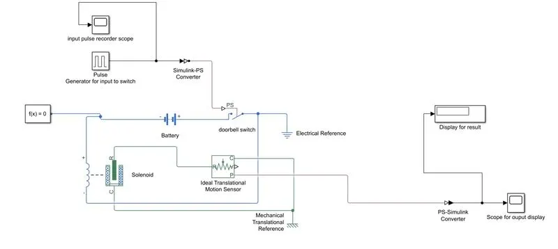
so now after connectecting them in one circuit by using pulse generater we provide input to the switch to control it,and i provide there one scope to monitor input there
at there pulse are set to
aplitude to 4
time period to 4 sec
pulse width kept as it is
and phase delay is 2 sec as per the requirement
as we knoow we cant directly provide sginal to switch by pulse generator to switch so now for convert simulink to ps coverter is used
threre is solenoid is used for to perform my door bell function so to know their output i used ideal traslation motion sensor and thier out is connected to display and recoder for out record
to solve this i need solver configuration is added and this performed for 60sec
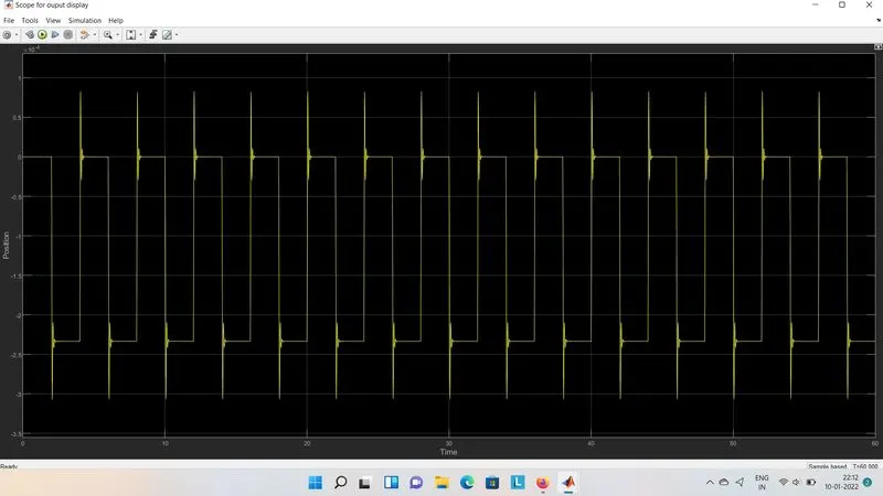
result :-desired output come with solenoid is operated as power input with help of switch
model:-
input:-

output:-
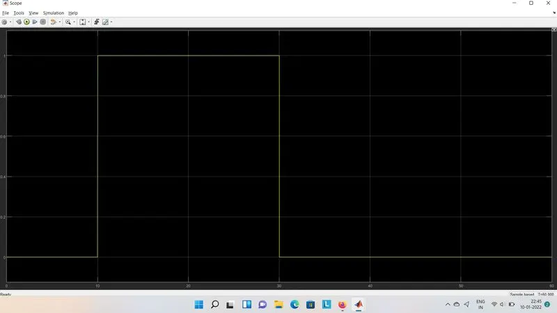
bell ring for 2 sec with 2 sec delay
problem statement 2:
Use a thermistor to sense the temperature of a heater & turn on or turn off the fan as per the below conditions:
Temperature source: 20 °C from 0 to 10 seconds, 27 °C from 10 to 30 seconds, 23 °C from 30 to 50 seconds
Fan conditions: ON if the temperature above 25 °C, OFF otherwise
answer:-
as per the given problem statement following block are used
1.thermistor
2.current senssor(ammeter)
3.battery
4.signal builder
5.switch
6.scopes
7.references
8.displays
9.converter
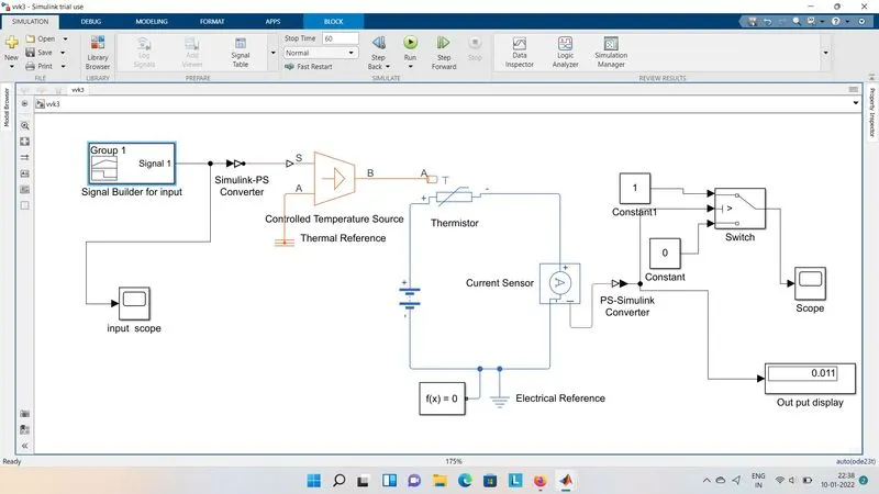
10.controlled temperature source
first of all connect the basic circuit
by taking thermistor with series battery and current sensing sensor after that
their connect one controlled temperature source after that their input is taken from singanl builder where we taken step signal with as per requirent to perform this as follwing givenn condition
their switch is used to get value if and only if it get more than 25 then it will be 1 or otherwise 0
on this condtions
is used their
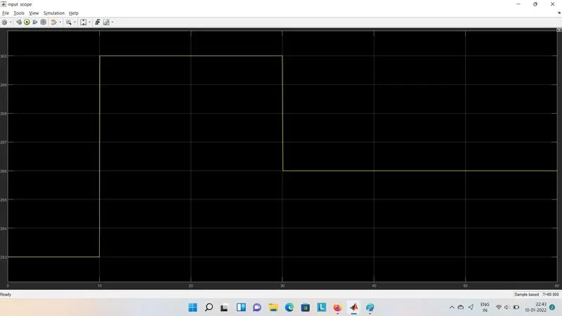
Temperature source: 20 °C from 0 to 10 seconds, 27 °C from 10 to 30 seconds, 23 °C from 30 to 50 seconds
Fan conditions: ON if the temperature above 25 °C, OFF otherwise
i need modified input signal builder as per this
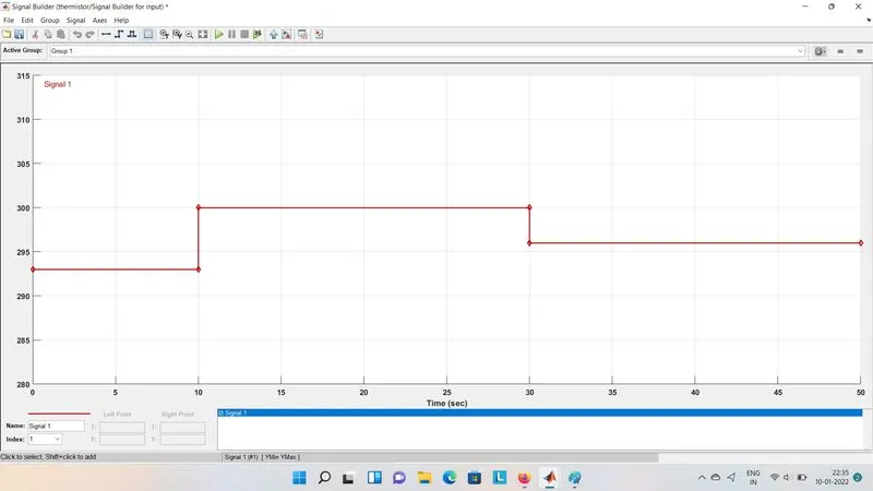
after that connect it with switch for with the constrant to modify it with to the output
thats why model look as the following
model:-
input given to the controlled temperature source
the final out are get as per follows
output is the fan is run for 10 to 30sec