Week -2
1. Simulink Model of a Doorbell Using a Solenoid:
Blocks required-
1. Battery- Electrical Power is given to the solenoid to energize.
2. Switch- To connect the source (battery) with the solenoid and associated system.
3. Solenoid- Generates a motion that causes the metal arm to hit the bell.
4. Electrical Reference
5. Pulse Generator- To connect the switch for a specified period of time i.e. for 2 seconds as given in the question.
6. Simulink-PS converter- the connection between electrical and physical systems.
7. Ideal Translational Motion Sensor- to detect motion and generate two parameters, velocity and position.
8. Mechanical Reference
9. Scope
10. Solver Configuration
11. PS-Simulink converter- the connection between physical systems and electrical systems.
The Simulink model diagram is shown in the below figure. Also, the parameters for the pulse generator is shown where the duty ratio is 40% of the 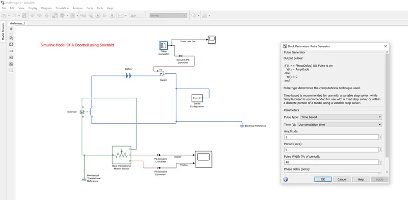
period i.e. 5 seconds which gives the pulse ON time = 2 seconds. So, the switch remains ON (closed) for 2 seconds and then goes OFF (open).
Process:
The battery is connected to a solenoid using a switch that remains ON (closed) for two seconds and then goes OFF (open) for the remaining time period. A pulse generator is used to make the switch ON-OFF where the parameters are taken; Period= 5 sec, Pulse width= 40%, this means the pulse of amplitude 1 will be available for 2 seconds and for the remaining time period i.e. 3 seconds, the pulse output is zero. A translational motion sensor is attached to the solenoid to detect the position change according to the switching conditions. As the switch is closed, the electrical signal is applied to the solenoid that generates a motion in one direction and as the switch is open, the position output of the solenoid comes back to the original place. Like this, the position is moved according to the switching conditions. The output can be seen through a scope and other blocks are connected as per the requirements.
Results:
Below given are the figures for the pulse generator output and motion sensor outputs i.e. velocity and position. 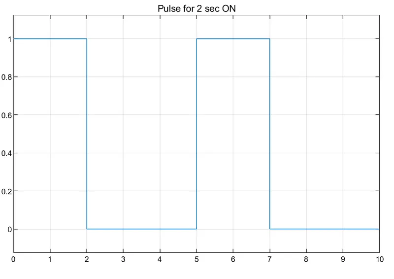
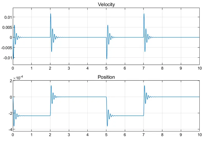
As can be seen from the diagram, as the switch is ON (the output of pulse generator is 1 from 0 to 2 seconds), the position value is 2*10^-4 and when the switch is OFF (the output of pulse generator is OFF from 2 to 5 seconds), the position value gets back to 0 value. As the simulation runs for another 5 seconds, the same process repeats and the position and velocity values are repeated to similar amount of time.
2. Using a thermistor to detect the temperature and turning ON-OFF a Fan:
Blocks required:
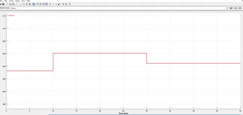
1. Signal Builder- The time range is changed to 50 seconds. The points of discontinuities are put as given in the question as follows;
| X axis (time in seconds) | Y axis (temperature in Kelvin) |
| t = 0 to 10 seconds | 293.15 |
| t= 10 to 30 seconds | 300.15 |
| t= 30 to 50 seconds | 296.15 |
2. Controlled Temperature Source- Controlled source means an external signal provided according to the user. This is generated through a signal builder block which is an input to it.
3. Simulink-PS converter
4. Thermistor- Temperature input through the signal builder and Simulink-PS converter block. Electrical input through a battery.
5. Battery
6. Resistor
7. Voltage Sensor
8. Electrical Reference
9. Solver Configuration
10. PS-Simulink Converter
11. Switch
12. Constant
13. Display
14. Scope
Below is the Simulink figure model.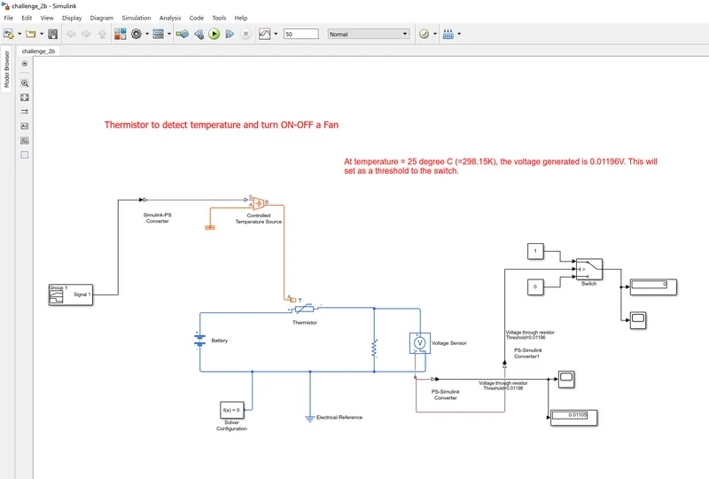
Process:
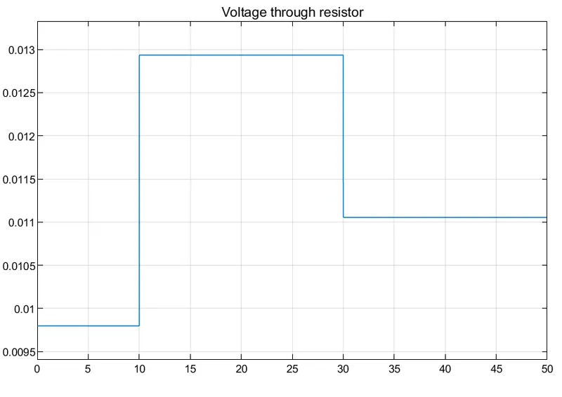
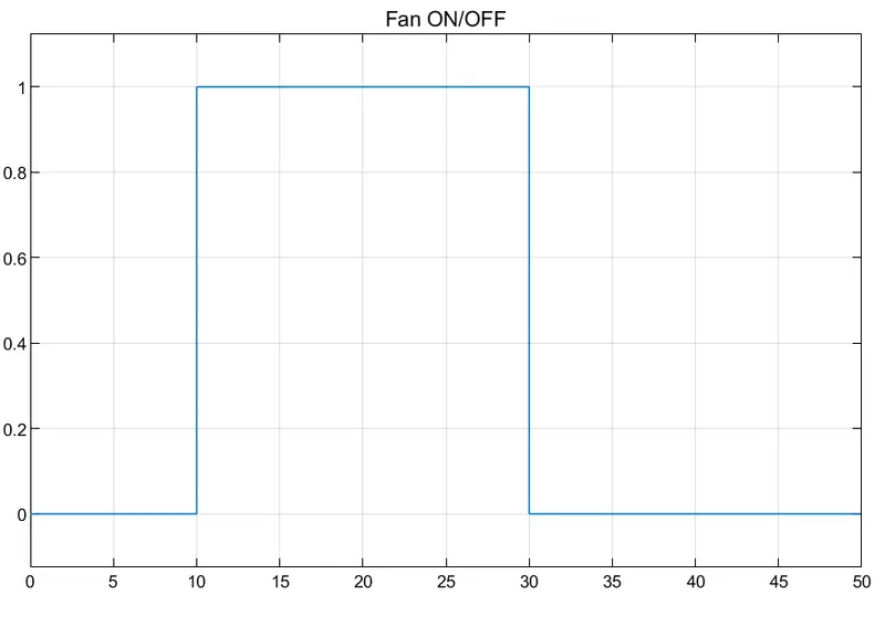
The signal builder block is used to generate the signal conditions as described in the blocks section. This acts as an input to the controlled temperature source where the temperature varies according to the time. This temperature signal is given to the thermistor block along with an electrical signal through a battery. The resistor is connected and the voltage sensor is used to detect the voltage appearing across the resistor. At first, the voltage generated at the resistor terminals at 25 degrees C (or 298.15 K) is checked by running simulation. The value of the voltage sensed through the voltage sensor is 0.01196V. This voltage acts as a threshold value to the switch as above this value, the first signal which is the constant block of value 1 will be connected. This also means that at a temperature above 25 degrees C, the switch will be connected to a constant block of amplitude 1 and hence, the high signal is used to display turning ON the fan. Otherwise, if the temperature is below 25 degrees C (298.15K), the switch will be connected to a 0 amplitude block that means turning OFF the fan.
Results:
The figure below shows the signal generated in a signal builder block, the voltage sensed across the resistor and the output of the switch. As the condition is given in the question i.e. as the temperature is over 25 degrees C or the voltage value is above a threshold value (between 10 to 30 seconds as seen in the signal builder block figure and the voltage across resistor signal), the switch remains connected to constant 1 that is signifying that the Fan should remain ON. In the remaining time, 1 to 10 seconds and 30 to 50 seconds, the temperature is below 25 degrees C and hence, the switch is connected to the third input which is constant 0 which signifies the Fan to be turned OFF.