Week -2
1.
AIM: To make a Simulink model of a Doorbell using a solenoid block.
OBJECTIVE: To observe the physical movement of the plunger when the switch is closed for 2 seconds and then released.
INPUT MODEL: The Simulink model for the Doorbell is shown below.
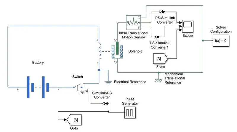
CONSTRUCTION: We have used the below blocks in our model.
- Battery: Supplies 12V DC (Internal resistance= 2 Ohm) to Solenoid (energizes the coil for the movenent of the plunger).
- Pulse Generator: Generates square wave pulses w.r.t time to the switch. The Pulse Generator is configured with parametrs: Amplitude=1, Period=4 secs, Pulse Width= 50% of period,Phase Delay=2 secs.
- Switch: To close the circuit when pulse is generated.
- Electrical and Mechanical Translational Reference: Acts as a ground point.
- Ideal Translational Motion Sensor: To sense the linear mechanical movement of the plunger.
- Scope: To monitor the signals.
- Solver Configuration: Used as a common reference point.
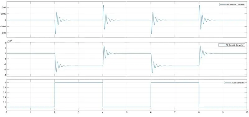
OBSERVATION: When the switch is closed as per the input received from the pulse generator of 2 secs, the electromagnet receives electrical power from the battery and pulls the metal arm of the Solenoid to hit the bell producing sound. Hence from the output of the scope as shown below, we can observe that from 0 to 2 sec when the pulse is not generated, there are no oscillations and from 2 to 4 sec when the pulse is genarated oscillations will be produced.
OUTPUT:
2.
AIM: To use a thermistor to sense the temperature of a heater & turn on or turn off the fan.
OBJECTIVE: To measure the temperature of Heater and turn ON/OFF the Fan as per below conditions.
- Temperature source: 20 °C (293.15 K) from 0 to 10 seconds, 27 °C (300.15 K) from 10 to 30 seconds, 23 °C (296.15 K) from 30 to 50 seconds
- Fan conditions: ON if the temperature above 25 °C (298.15 K), OFF otherwise
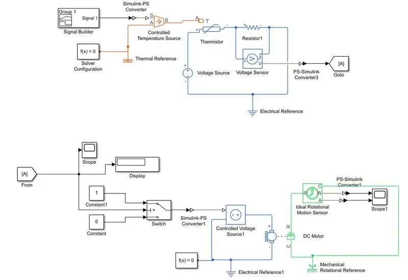
INPUT MODEL: The Simulink model for the Heater, Thermistor and Fan is shown below:
The Signal Builder configuration is shown below for various temperature values (Kelvin) w.r.t time.
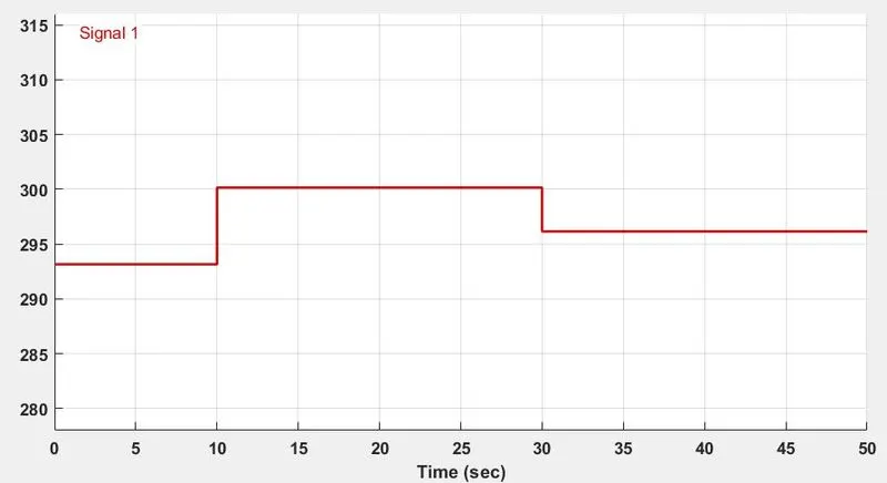
CONSTRUCTION: We have used the below blocks in our model.
- Signal Builder: The temperature ranges (in Kelvin) w.r.t time are fed to the thermister using Signal Builder as shown above.
- Controlled Temperature Source: This block maintains a controlled temperature difference regardless of the heat flow rate.
- Thermistor: NTC Thermistor senses the temperature using the B-parameter equation.
- Voltage Source: Supplies 5V DC to drive the Thermistor.
- Voltage Sensor: This block converts voltage measured between any electrical connections into a physical signal proportional to the voltage.
- Thermal, Electrical and Mechanical Rotational Reference: Acts as a ground point.
- Scope and Display: These are used to represent the Voltage from the Voltage Sensor.
- Switch: Switch is configured in such a way that when the Voltage from the second input port (control portis) >= 0.004616 V, the switch makes the circuit. The first and third input ports are data ports i.e. 0 and 1 which represents the minmum and maximum reference values.
- Controlled Voltage Source1: This block maintains the specified voltage at its output regardless of the current passing through it.
- DC Motor: This block represents the Fan which converts the electrical energy to mechanical energy.
- Ideal Rotational Motion Sensor: This is used to measure the angular velocity or angle in a mechanical rotational network.
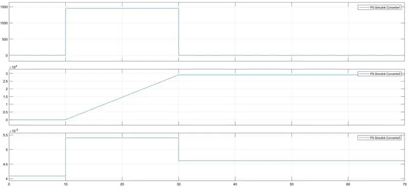
OBSERVATION: The below output graph shows that the FAN runs for a duration of 10 to 30 secs when switch is ON i.e. when the Temperature is above 25 °C (298.15 K) and apart from this duration the FAN is OFF.
OUTPUT: