Week -2
Question 1 : Make a simulink model for doorbel using solenoid
for making the model follwing blocks have been used
1. pulse generator
2. switch
3. solenoid
4. ideal translational motion sensor
5. Mechanical Translational reference
6. electrical reference
7. scope
According to the curcuit given and also the principle of doorbell, when the switch is closed then the solenoid gets magnetized and pulls the striking arm which hits the bell. Hence, we can see from the simulink schematic, battery supply is going to solenoid when switch is on.
Matlab Schematic: simulation time of 30 sec has been taken. Battery voltage is same as solenoid i.e 50 volts.
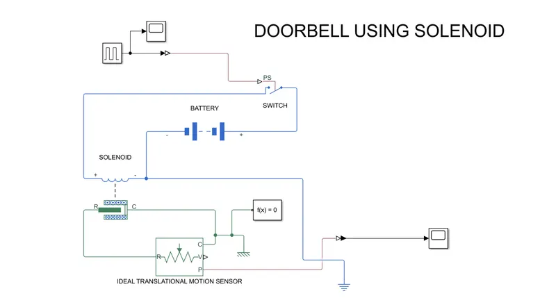
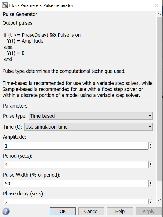
input to switch from pulse generator : Pulse generator has been used to give input to switch at regular interval of time.
it's parameters are taken as follows :
Results :
input to switch 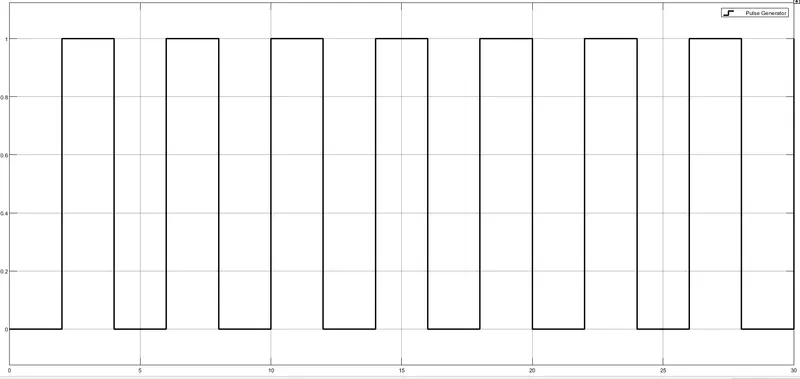
output or position of plunger :
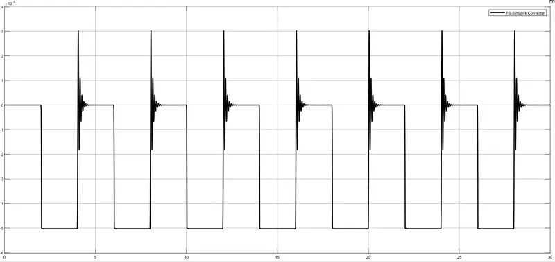
We can see from output that when the switch is on then strinking strip position is changing in negative direction means R is approaching C or striking strip is hitting the bell. and when the position is at zero then switch is off or vice versa. Initially, there is disturbance which gets settled after few milli seconds.
Question 2 : Use a thermistor to sense the temperature of a heater & turn on or turn off the fan as per the given conditions
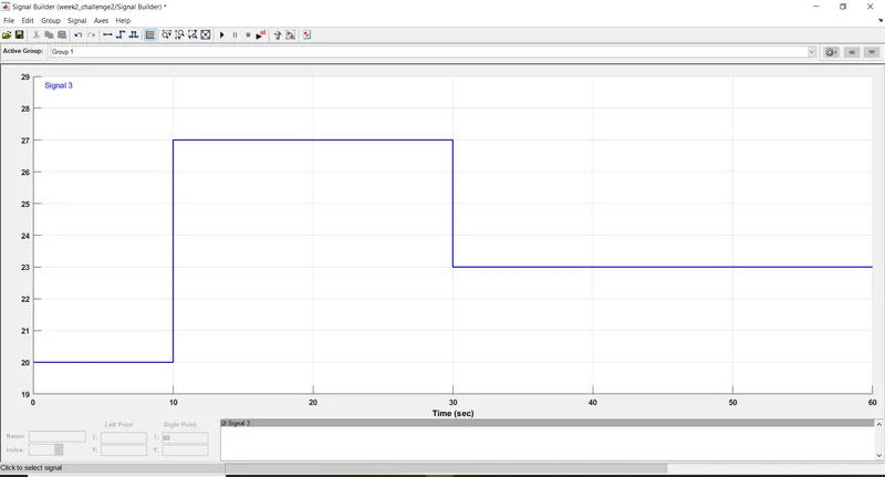
which is -- Temperature source: 20 °C from 0 to 10 seconds, 27 °C from 10 to 30 seconds, 23 °C from 30 to 50 seconds
Fan conditions: ON if the temperature above 25 °C, OFF otherwise
Blocks Used in simulink model are :
1. signal builder
2. controlled temperature source
3. thermal reference
4. thermistor
5. battery supply
6. resistance
7. voltage sensor
8. switch
9. scope
10. simulink to ps converter
11. ps to simulink converter
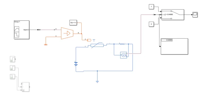
The schematic of matlab model is shown in below figure : We can see that a resistance of value 1 ohms has been used in series with thermister. The voltage across series resistance is used for turning on or off the fan. we can see from the schematic that a voltage of 0.04985 volts has been shown which is the voltage at room temperature i.e 25 degree celcius. hence when the voltage across series resistance goes above than this then fan becomes on and off otherwise.
Input to the controlled temperature source : temperature input of 20 degree celcius from time 0 to 10sec , 27 degree celcius
from 10 to 20 sec and 27 degree celcius from 30 to 50 sec has been taken.
Results :