Week -2
1) Challenge : 1
Aim: To make a simulink model of a door bell using solenoid blocks.
Blocks used:
- Pulse Generator - set for 2 sec (to keep the switch in closed position for 2 sec)
- Simulink to PS converter - to convert the simulink signal to physical signal
- Switch - to control the electrical sin=gnal
- Battery - for electrical source
- Solenoid
- solver configuration
- Force sensor
- Electrical Reference
- Mechanical Reference
- Ps to simulink converter
- Scope
Simulink Model:
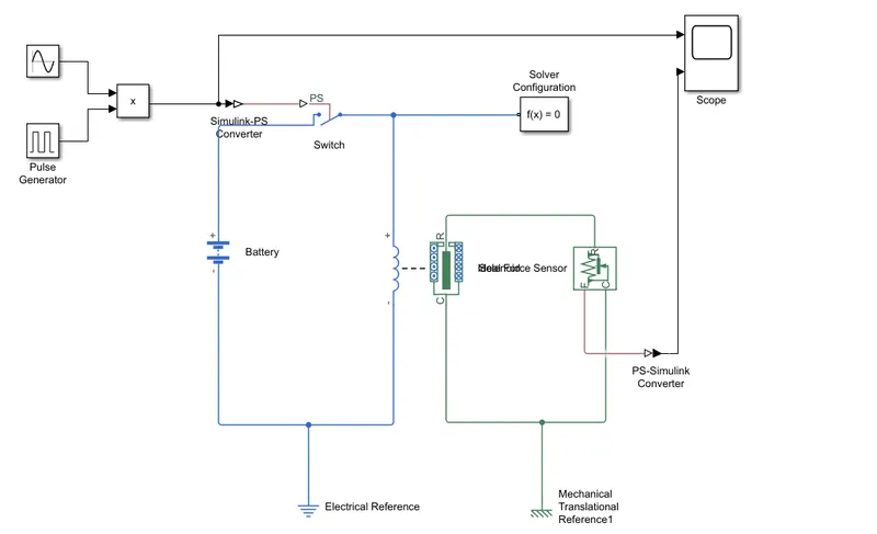
Description:
- Arrange/connect the simulink blocks as shown in the above simulink block representation.
- The battery is connected to a single pole single throw switch. battery provides the electrical signal or power for the solenoid to move in the desired position and the switch is used to control the electrical signal provided by the battery before reaching to the solenoid.
- A solenoid is then connected from the SPST switch which act as the plunger or metal arm which hits the bell on given an electrical siignal.
- in our case we have to set the time for the switch to be in on condition for 2 sec, for acheiving that equation we have to use a pluse generator, sine wave block, a two input product block and a simulink to PS converter.
- Pulse generator is used to produse the electrical pulse for the desired time. In our case we are setting the pulse for 2 sec by changing the value of period and pulse width (10 & 20) respectively.
- Sine wave is used to cut the electrical pulse periodically to give an non continious sound for two sec. (this block is only used as an modification in case you dont want to ring your door bell continuously.
- as our output signal should be an product of the parameters entered in pulse generator and sine wave we use an two input product block to achieve this equation
- as these both are simulink blocks it is necessary to converth them to a pysical system before connecting it to a switch, hence we use an simulink to a physical converter here.
- A solver and an electrical reference is connected as shown in the block representation to specify the solver parameters and to ground the electrical elements respectively.
- The output of the solenoid is connected to a force sensor to sense the og get the output whn the plunger hits the bell.
- This force is then converted by using a PS to simulink converter and connected to a scope where we get the graphical representaion of our output as shown below.
- All the mechanical blocks should be clamped using a mechanical translational reference.
Simulink Output;
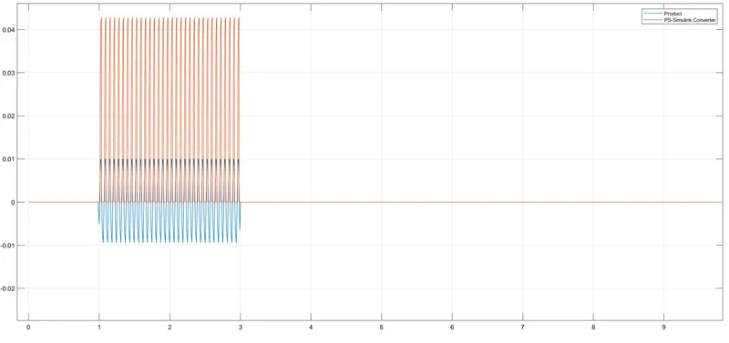
- After a time delay of 1 sec the switch receives the electrical signal for 2 sec . During that time the solenoid gets energised and hits the bell but as we have connected a sine wave the solenoid gets energised and de energised according to the sin wave and we gets an output as shown above.
2) Challenge : 2
Aim : To turn On/Off a fan by sensing the temperature of a heater using a thermistor.
Blocks used :
- Signal Builder
- Temperature source
- Temperature sensor
- Thermistor
- Current sensor
- Battery
- Switch
- Universal Motor
- Torque sensor
- Scope
- Electrical, Mechanical & hermal reference
- Solver configuration
- Scope
Simulink Model :
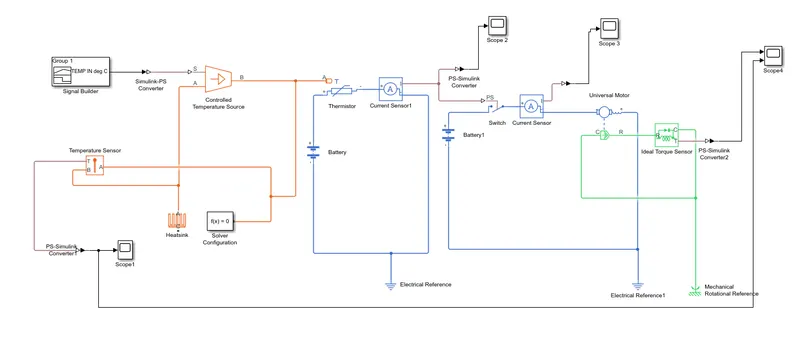
Description :
- Connect all the blocks as shown in the above simulink model.
- Signal builder is used to create three input signals i.e three temperature in our case by plotting the required values in the signal builder graph.
- The signals from the signal builder block is controlled by a temperature controller, which can be sensed using a temperature sensor and output can be viewed using a scope as shown below
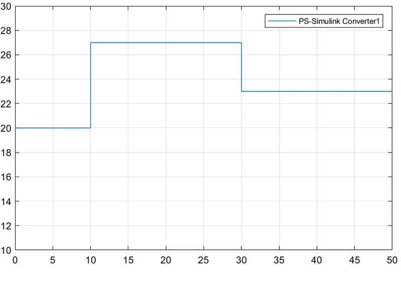
- The output from the temperature source is connected to a thermistor which is used to sense the temperature inputs at the given time intervals.
- The thermistor circuit consists of a battery and a current sensor to know the difference in current value at each temperature time intervals as shown below.
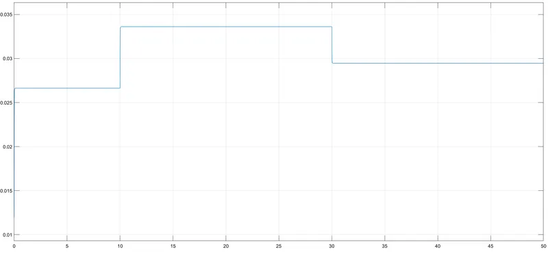
- Now the output of the thermistor is connected to a universal motor which act as a fan in our case. The rotation of the motor is controlled by a switch whose threshold is set to the required values for the motor to run at a specific input temperature . From the above graph we can set our threshold to 0.034
- Now the rotation of the motor can be sensed by a torque sensor which can be displayed on a scope as below.
Simulink Output: 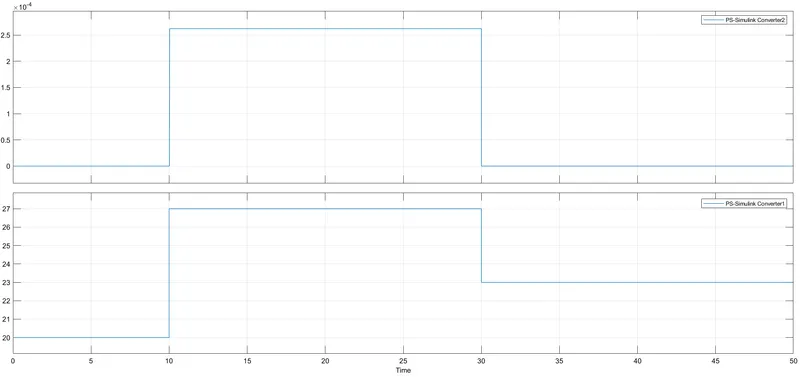
- The above graph shows the motion of the fan at various time intervals and the below graph shows the temperature at different time intervals.
Output:
- Fan will be turned on only at temperature 25 deg C and above as we set the threshold to 0.034