Automated Cooling System and Simulating an Electric Bell
- Aim : Simulating an electric bell and modelling an automated cooling fan system for a heater using thermistor.
- Objective and Workflow :
- Creating a model to simulate the behaviour of an electric bell using an solenoid block and observing the motion of plunger.
- Modelling an automated cooling fan system for a heater, keeping the temperature under a predefined temperatue measure.
Workflow :
- In the electric bell model we try to follow up the following circuit of an simple electric bell :
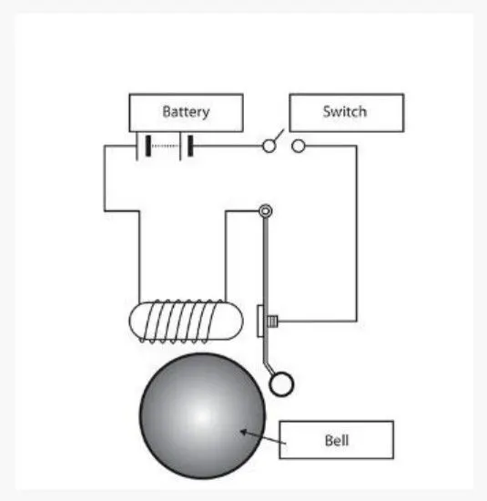
- We will use the solenoid block which after excitation moves the plunger. In the model to oscillate the plunger we are using a pulse generator source connected to a switch controlling the power given to solenoid.
- We then use the translation motion sensor to measure the movement of the plunger which then displayed onto the scope.
- In the second model we use the thermistor to measure the temperature of the heater. Using the volatge sensor we measure the decreasing potential across thermistor.
- According to the potential across thermistor the switch block passes predefined inputs to the controlled voltage source powering DC motor.
- We use the torque sensor to measure/sense the motion of the motor with time, displayed onto the scope.
- Simulink Models & Explanation :
Electric Bell Model :
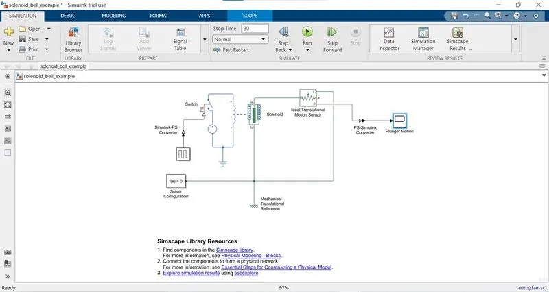
- The main component of this model is solenoid block which eventually is also a main component of electric bell. The concept to produce sound in electric bell is attracting a metal plunger by an electromagnet(solenoid) so to hit the gong and breaking the circuit. The spring connected to the plunger to revert its position, also connecting the circuit again.
- So to mimic the above behaviour, the solenoid block needs to be excited in a periodic manner. The solenoid block implements the electric and mechanical behaviour of a solenoid. It needs DC power supply for excitation and we set the force, stroke parameters to control the movement of the plunger untill we hold this condition X2/X1>sqrt(F1/F2). We can also assign mechanical parameters like spring and damper cofficient for controlling the dynamics of plunger while returning to its position.
- The oscillating movement of the plunger can be achieved if we switch on and off in a oscillating manner for which we use the switch block. This switch will be in closed state if the physical signal is above the threshold otherwise will be in open state.
- We need to provide an oscillating physical signal to the switch for which we use the pulse generator block but its output is a simulink signal which will be converted to a physical signal using the simulink-ps converter block.
- We connect the mechanical port C of the solenoid block to mechanical translation reference so to have a definite measure across the mechanical ports C and R. As we know to measure anything we need to have a reference from which we measure or compare the other quantity to quantify. The solver configuration is connected near this reference.
- Now we have plunger oscillating but to measure or sense its movement we need to connect the translation motion sensor to mechanical port R of the solenoid. As we know to measure, we need a reference so we connect the port C of motion sensor to the translation reference as well.
- The translation motion sensor block will measure the motion across the port R, C and give physical signal of position and velocity. As we are measuring the position so we take the position signal to a ps-simulink converter which can be feeded into a scope.
Simulation, Parameters & Results :
- Talking about the parameters, starting off with the pulse generator the period of the pulse is set for 4 seconds with 50% pulse width so to achieve a 2 sec. high for a 4 sec. pulse. The amplitude is set to 2 and for time using the simulation time.
- As we doing physical modelling we need to convert the simulink signal from the pulse generator to physical signal using the simulink-ps converter whose parameter are set to default. Now this signal is given to the switch block for controlling the on-off state.
- The parameters of the switch block are also kept to default except the threshold which is set to 1. As we know the pulse generator will provide a physical signal of amplitude 2 units which is above the threshold resulting in closing the switch for 2 seconds. Also the switch will be in open state for the next 2 sec. as the physical signal will be 0, below the threshold.
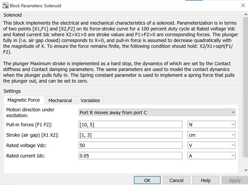
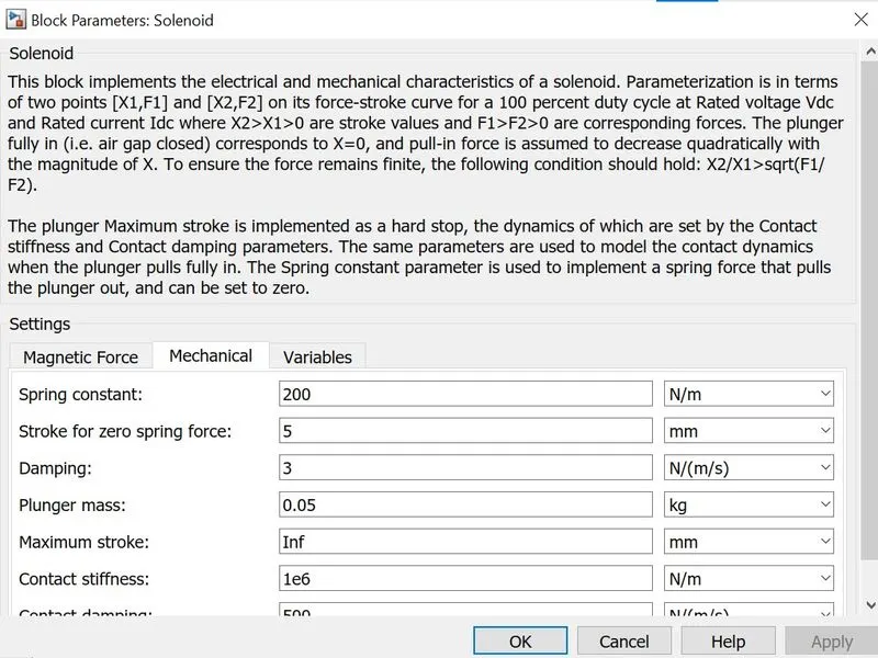
- We are using the DC power source to excite the solenoid. The switch is connected between the source and solenoid. We also need to give electrical reference to act as ground, completing the circuit. We changes the stroke and pull-in-forces vectors and also to control the dynamics of the plunger while reverting back we changes the spring and damping cofficients accordingly. The solenoid block parameters are set as the following :
- The movement of the plunger is across the mechanical ports R-C in which the port C is connected to the translation reference and the port R is connected to motion sensor. The motion sensor port C is also connected to the translation reference.
- The output from the motion sensor is a physical signal which if we want to see/anaylse need to be feeded to scope but before that we convert it to a simulink signal using the ps-simulink converter.
Results :
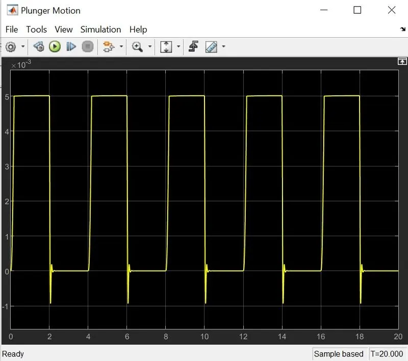
- The simulation time is set for 20 seconds. So on the y-axis we see the displacement of the plunger with time being on x-axis. According to the pulse sent to the switch, it will remain in closed state for first 2 sec. then will be in open state for the next 2 second.
- We see from the scope that the plunger has a displacement of 5 mm in the first 2 sec. as soon as the power is provided to the solenoid. After the plunger has reached the specific position, it stays there due to the pulling/pushing forces will be acting for 2 seconds.
- After 2 seconds the switch will open and there will be no pulling forces on the plunger. So it starts it journey back to its initial position because there is spring and damper connected to it to pull/push it back to initial position.
- We see that the plunger after releasing from the pull position, it carries some momentum due to tension in the spring so there are some damping oscillations before it settle down to the reference position. We can control these damping oscillations by changing the parameters in the solenoid block. In the current scenario if we increase the stiffness of the spring by inceasing the value of spring constant then the plunger will move less in the negative y-direction.
Automated Cooling System Model :
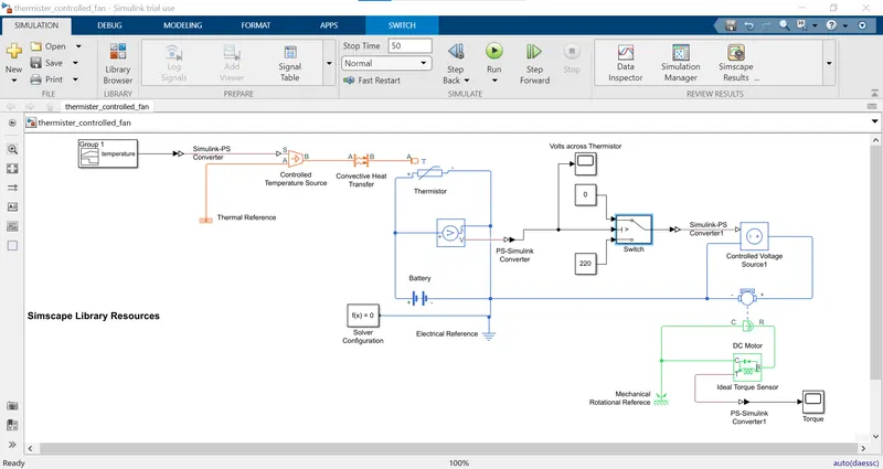
- The idea behind the model is that when the temperature goes above 25 degree celsius then the fan should autmatically turned on and after the temperature goes again down below 25 then it should turn off.
- The model contains these main components being generating different temperature conditions, sensing these temperature conditions, automatically switching the motor, sensing the motor torque.
- For creating different temperature conditions, we are using controlled temperature source which will be controlled by a custom physical signal. We created different temperatures but to transfer that conditions in an environment we use the convective heat transfer block so to transfer these temperature conditions as one of the heat transfer methods.
- The custom physical signal is created using the signal builder block. As we are asked for specific temperature conditions for different time, showing below are these conditons :
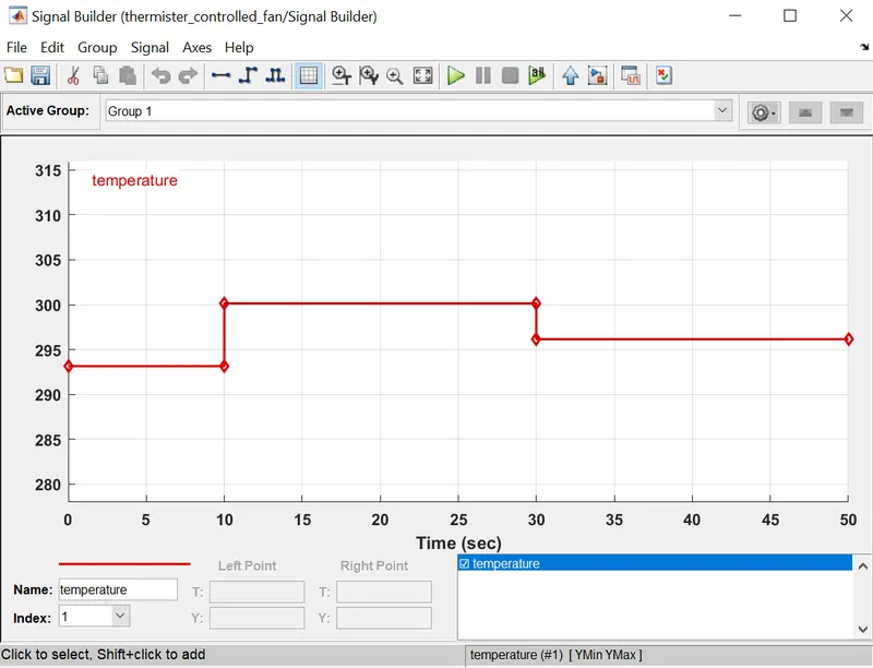
- As we see for the first 10 seconds the temperatue is 20 degree, for the next 20 seconds it is 27 degree and for the next 20 seconds it is 23 degree celsius. We then feed this signal to the simulink-ps converter which will be given to the controlled temperature source.
- The second main part comes with sensing the temperature so we use the thermistor block. The concept of the thermistor is that if temperature rises its resistance(electic property) decreases. The thermistor is of two types one is NTC(negative temperature cofficient) and other is PTC(positive temperature cofficient). Basically one's resistance decrease with increase in temperature and other's one increases with increase in temperature.
- We are using a NTC thermistor so with increase in temperature its resistance is going to decrease so we got a component to measure that can act as scale for change. We gonna measure the potential across the thermistor which will decrease as the temperature increases.
- We use a voltage sensor to measure the potential across the thermistor. The positive end of the sensor is connected to the positive end of the thermistor and so as the negative. We use a DC source to create potential across the thermistor and for completing the circuit, use the electrical reference block to act as ground.
- The output from the voltage sensor is a physical which we need to convert into simulink signal so to feed it into the last main component of the model which is automating the switching of fan.
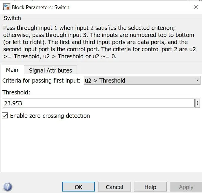
- So to do the automation we use the switch block, defining its behaviour we can say that it passes one of the two signals if the threshold condition is met. This block is like an multiplexer, have three inputs u1, u2, u3 and one output. It has a parameter called threshold which act as threshold literally triggering the switch to pass either u1 or u3. So if the input signal at u2 is greater than set threshold then the input u1 will directed as the output otherwise u3 is directed as the output.
- So at the output of the switch block we have a controlling signal that we feed into a controlled voltage source to power up the motor. But before that we again need to convert it into a physical signal as the controlled source needs one.
- Now we just need to connect a DC motor block to the voltage source which is actually a fan without fan blades. The analysis part comes in now, so to see that the motor is running at the right time and temperature or not, we use the torque sensor. Actually the DC motor block outputs torque across the port R-C.
Simulation, Parameters & Results :
- The signal builder is used to create custom temperature signal. So while setting it up we take temperature on the y-axis and time on x-axis. The time needs to be increased to 50 seconds and we need to put temperature in kelvin as the other blocks have it as a default setting. Then this signal is converted to a physical signal before we feed it to controlled temperature source.
- The controlled temperature source is an ideal energy source in a thermal network which create a temperature difference across the ports A-B. The temperature source is controlled by our custom temperature signal. As it is created across ports A-B, we need to connect the port A to the thermal reference.
- Then we need to transfer this heat energy for that we use the convective heat transfer block whose parameters are kept to default. The heat is now transmitted to the thermistor which will sense the temperature change.
- As the temperature changes the resistance is going to change so do the volts across it. We measure the change in the potential using the voltage sensor. The output of the sensor is converted into a simulink signal and feeded into the scope for analysis.
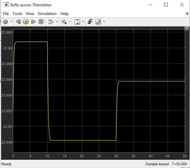
- The temperature condition for motor to start is at 25 degree celsius, if the temperature goes above 25 the motor should start rotating and as it comes again at 25 the motor should stop rotating.
- So as we are using this potential as the threshold for the switch block, we need to measure the potential at 25 degrees which in our model is 23.953 volts. So if the potential goes below this mark the switch block will pass the third input which we give through constant block.
- The switch block will pass input 1 and 3 according to the conditions at input 2, as of our requirements we need to power the motor or keep it off. So we use two constant blocks to either pass 220 or 0 as the output of the switch block.
- The output of the switch block is again converted into physical signal to control the voltage source, in our case basically turning it on and off. The parameters of the DC motor are kept to default.
- The ground is provided by the electrical reference for the thermistor circuit and also for the motor circuit. The mechanical port R of the motor is connected to the port R of the torque sensor and the port C of both is connected to the mechnical rotational reference. Notice that for angular motion we need to use rotational reference. The output of the sensor then feeded into a scope after converted into a simulink signal.
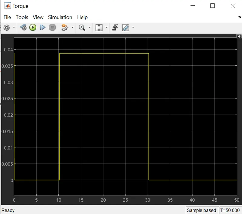
- We need to see that whether the motor produces torque when the temperature goes above 25 degrees and stop producing torque when the temperature goes down again.
- According to our custom temperature signal, the temperature goes above 25 for the time between 10 to 30 seconds and stays below 25 for the rest of the time. We can see that the motor is producing torque for the time period of 10 to 30 seconds and stays down for the rest of the time.
- Simulink Models :
https://drive.google.com/drive/folders/1Mr-HidIIpCFwlhyWjanBju4s1UUjGrAO?usp=sharing