Week -2
1) Title:- Make a Simulink model of Doorbell using solenoid block
A) Simulink Block Diagram:-
Simulink Doorbell Model is shown below, slx file is attached and Simulink Blockdiagram explanation is given below.
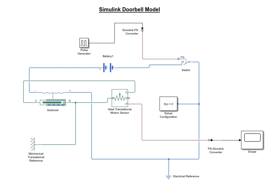
B)Simulink Block Diagram Explanation:-
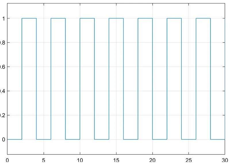
1) Pulse generator is used to provide square wave signal to the switch to satisfy the condition i.e 0.5 sec off and then released the switch.
2) Simulink-PS converter is used to convert the sumulink signal to physical signal.
3) Switch is used for ON and OFF operation, ON and OFF time is depend upon the pulse generator signal.
4) Battery is used to supply all the block in the model.
5) solenoid block is convert the electrical energy into mechanical energy. Used as per the question to hold the plunger when switch is closed and released the plunger when switch is open.
6) Ideal Translation Motion sensor is used to sense the movment of plunger and giving output to the scope.
7) PS-Simulink converter is used to convert the physical signal into simulink signal.
8) Scope is used to showing the result of plunger movment to the observer in the form of graph.
9) Solver configuration is used to specifies the solver parameter that model need before the simulation.
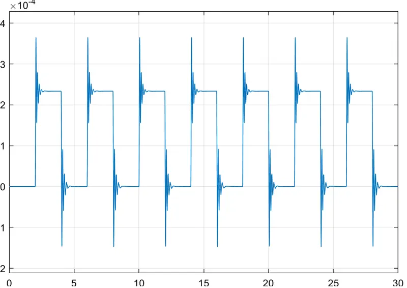
c)Results :- The switch is closed for a 2 second and thenreleased. We will record the value with help of scope and the result is shown below.
D)Conclusion:-
Giving input as time period for 2 second in the pulse generator to open and closed the switch. When the switch is closed the solenoid block recieves the power from battery to move the plunger port R to port C and produced the sound.
-----------------------------------------------------------------------------------------------------------------------------------------------
2) Title:- Use Thermistor to sense the temperature of heater and turn ON OFF the fan
A) Simulink Block Diagram:-
Simulink Block Diagram is shown below, slx file attached and block diagram explanation is given below.
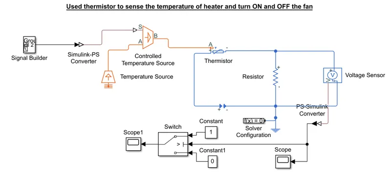
B)Simulink blockdiagram explanation:-
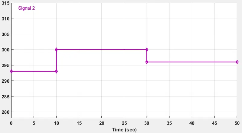
1) Signal builder is used to create a signal according to question to satisfy the given condition.
i.e 20°C 0 to 10 sec
27°C 10 to 30 sec
23°C 30 to 50sec
2) Simulink ps converter is used to convert the simulink signal into Physical Signal to give to the Controlled Temperature Source.
3) Temperature Source is used to provide the heat. To obtain the condition i.e Fan is ON if the Temperature is above 25 degree celcious.
4) Thermistor is used to sense the temperature.
5) Voltage sensor is convert the voltage signal to physical signal which is proportional to the voltage.
6) Threshold value is obtained by the voltage sensor. That threshold value is used by the switch to display '1' and '0' using the if-else condition.
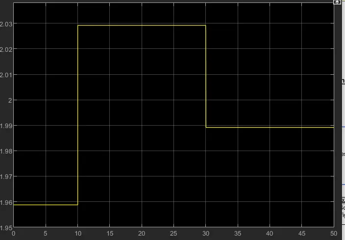
7) PS- Simulink converter is used to convert physical signal into simulink signal.
9) Scope is used to showing When the fan is ON and OFF.
C)Result:- The Result is Showing that the Fan is ON during 10 sec to 30sec and before the 10 sec and after the 30 sec Fan is OFF because only 10sec to 30sec temperature is greater than 25°C.
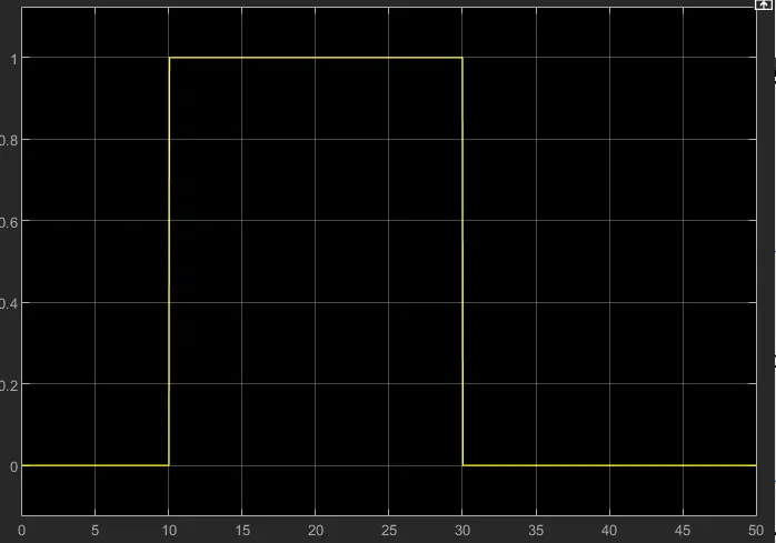
D)Conclusion:- Hence the given problem was simulated according to the given conditions. i.e sense the temperature, if it is greater than 25°C then switch ON the fan Otherwise switch OFF the fan.