Week -2
Question1
Aim
To make a Simulink model of Doorbell
Introduction
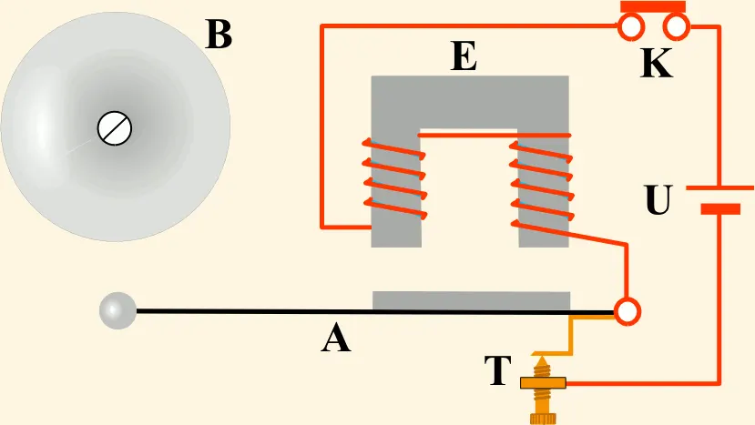
figure 1
An inductor is a passive electronic component which is capable of storing electrical energy in the form of magnetic energy. Basically, it uses a conductor that is wound into a coil, and when electricity flows into the coil this will generate a magnetic field.
The magnetic field is produced when the switch is closed and pulls the plunger towards the mechanical part and once the switch is opened the plunger moves to its intial position.
Blocks used
Pulse Generator

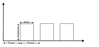
The Pulse Generator block generates square wave pulses at regular intervals. The block waveform parameters, Amplitude, Pulse Width, Period, and Phase delay, determine the shape of the output waveform. The following diagram shows how each parameter affects the waveform.
Battery
The Battery block represents a simple battery model. It is the source

Scope

Display signals generated during simulation
Solenoid block

The Solenoid block represents the electrical characteristics and generated force for the solenoid.
Ideal Translational Motion Sensor

The Ideal Translational Motion Sensor block represents a device that converts an across variable measured between two mechanical translational nodes into a control signal proportional to velocity or position.
Mechanical Translational Reference

The Mechanical Translational Reference block represents a reference point, or frame, for all mechanical translational ports. All translational ports that are rigidly clamped to the frame (ground) must be connected to a Mechanical Translational Reference block.
Solver Configuration

Each physical network represented by a connected Simscape™ block diagram requires solver settings information for simulation. The Solver Configuration block specifies the solver parameters that your model needs before you can begin simulation.
Electrical Reference block

The Electrical Reference block represents an electrical ground. Electrical conserving ports of all the blocks that are directly connected to ground must be connected to an Electrical Reference block. A model with electrical elements must contain at least one Electrical Reference block.
Simulink-PS Converter

The Simulink-PS Converter block converts the input Simulink signal into a physical signal. Use this block to connect Simulink sources or other Simulink blocks to the inputs of a Simscap physical network.
working of the simulink model
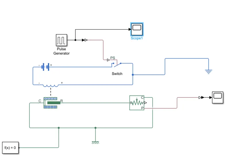
Simulink block
1) Pulse generator is used to generate the wave as per the requirement which is show in the table below
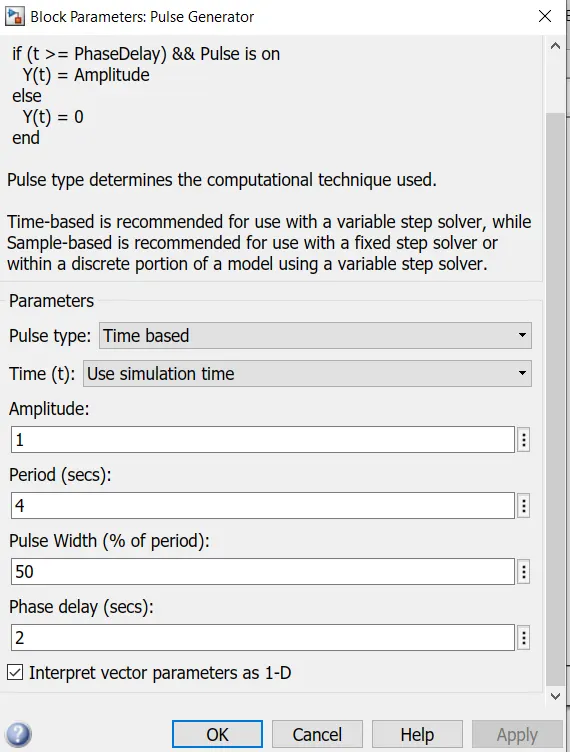
Generation of the wave
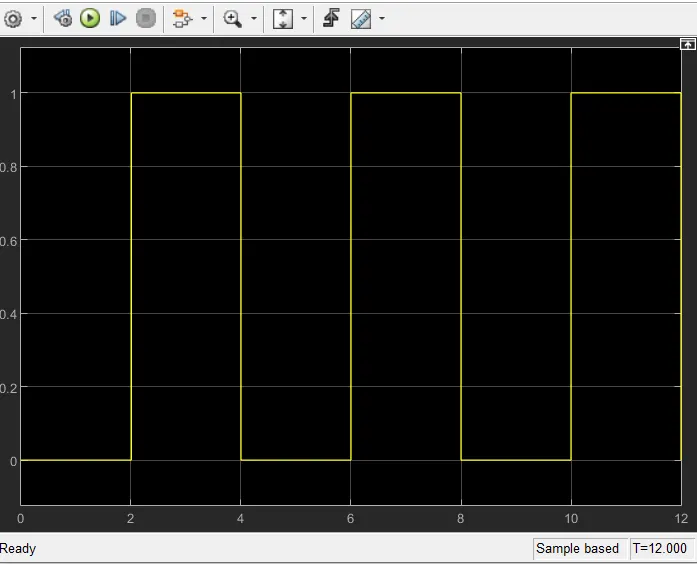
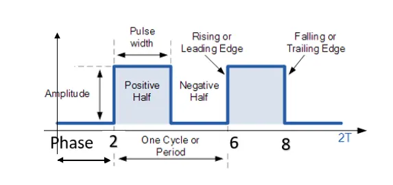
By generating the wave as shown above we can Create a situation where the switch is closed for 2 seconds and then released.
2) When switch is closed the current flows from the source (battery).
3) As the current flows over the coil it generates the magentic field
4) The magentic field produced pulls the pulnger towards the bell
Result
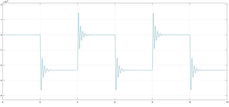
The plot shows the position of plunger
for 0-2secs the switch is in off condition
for 2-4secs the plunger is negavtive and indicates that it is towards the bell
and the Oscillation of the plunger can be reduced by increasing the damping value as show in the tabel below
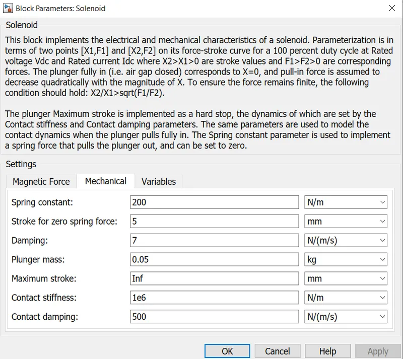
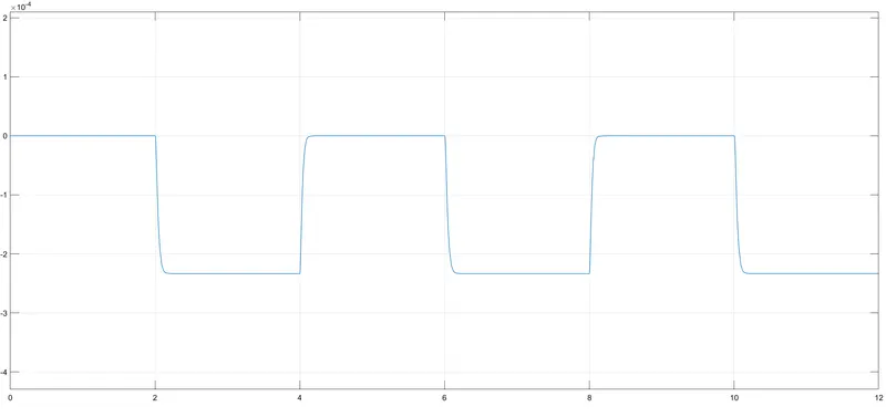
Plot after increasing the damping value
Question 2
Aim
Use a thermistor to sense the temperature of a heater & turn on or turn off the fan as per the below conditions
20 °C from 0 to 10 seconds,
27 °C from 10 to 30 seconds,
23 °C from 30 to 50 seconds
Fan conditions: ON if the temperature above 25 °C, OFF otherwise.
Introduction
A thermistor is a thermal resistor - a resistor that changes its resistance with temperature.
There are two kinds of of thermistors, NTC (negative temperature coefficient) and PTC (positive temperature coefficient). In general, you will see NTC sensors used for temperature measurement. PTC's are often used as resettable fuses.
NTC Thermistor - When the temperature of a thermistor increases, its resistance decreases significantly. Typically, for every 1oC rise in temperature, there will be a 5% decrease in their resistance. So their sensitivity is very high.
PTC thermistors- When a current flows through a PTC the heat generated raises the temperature of the PTC. When the temperature of a thermistor increases, its resistance increases.
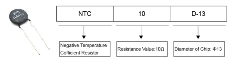
NTC 10D-13 explained below
Blocks used
Signal Builder

The Signal Builder block allows you to create interchangeable groups of piecewise linear signal sources and use them in a model.
Controlled Temperature Source

The Controlled Temperature Source block represents an ideal source of thermal energy that is powerful enough to maintain specified temperature difference across the source regardless of the heat flow consumed by the system.
Thermistor

The Thermistor block represents an NTC thermistor using the B-parameter equation.
Thermal Reference

The Thermal Reference block represents a thermal reference point, that is, a point with an absolute zero temperature, with respect to which all the temperatures in the system are determined.
Resistor

The Resistor block models a linear resistor, described with the following equation:
V=I·R
where:
-
V is voltage.
-
I is current.
-
R is resistance
Electrical Reference
The Electrical Reference block represents an electrical ground. Electrical conserving ports of all the blocks that are directly connected to ground must be connected to an Electrical Reference block. A model with electrical elements must contain at least one Electrical Reference block.
Battery
The Battery block represents a simple battery model. It is the source
Scope
Display signals generated during simulation
Solver Configuration
Each physical network represented by a connected Simscape™ block diagram requires solver settings information for simulation. The Solver Configuration block specifies the solver parameters that your model needs before you can begin simulation.
PS-Simulink Converter

The PS-Simulink Converter block converts a physical signal into a Simulink output signal. Use this block to connect outputs of a Simscape physical network to Simulink scopes or other Simulink blocks.
Simulink-PS Converter
The Simulink-PS Converter block converts the input Simulink signal into a physical signal. Use this block to connect Simulink sources or other Simulink blocks to the inputs of a Simscap physical network.
Voltage Senso

The Voltage Sensor block represents an ideal voltage sensor, that is, a device that converts voltage measured between two points of an electrical circuit into a physical signal proportional to the voltage..
Switch

The Switch block passes through the first input or the third input signal based on the value of the second input. The first and third inputs are data input. The second input is a control input. Specify the condition under which the block passes the first input by using the Criteria for passing first input and Threshold parameters.
Constant

The Constant block generates a real or complex constant value signal. Use this block to provide a constant signal input.
Display
The Display block shows the value of the input data.

Controlled Voltage Source

The Controlled Voltage Source block represents an ideal voltage source that is powerful enough to maintain the specified voltage at its output regardless of the current flowing through the source.
DC motor

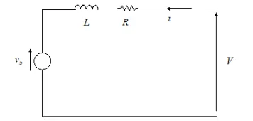
The DC Motor block represents the electrical and torque characteristics of a DC motor using the following equivalent circuit model:
Ideal Rotational Motion Sensor

The Ideal Rotational Motion Sensor block represents an ideal mechanical rotational motion sensor, that is, a device that converts an across variable measured between two mechanical rotational nodes into a control signal proportional to angular velocity or angle.
Mechanical Rotational Elements

The Mechanical Rotational Reference block represents a reference point, or frame, for all mechanical rotational ports.
working of the simulink model
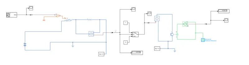
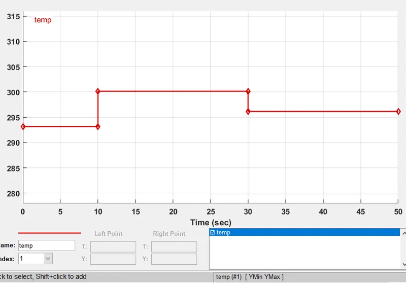
1) The input signal is given as shown below which represents 20 °C from 0 to 10 seconds, 27 °C from 10 to 30 seconds and 23 °C from 30 to 50 seconds.
all the values are converted to kelvin as all the thermal blocks are in kelvin by default.
2) The resistance of NTC thermistor will decrease as the temperature increases.
3)Resistance is connected in series with the thermistor to know the evaluate threshold voltage and also to keep the circuit in balanced way when there is sudden change in the temperature.
4)once the threshold voltage is know for 25 degree Celsius the threshold value can be mentioned in the switch.
5)switch open's if the threshold value is equal too or greater than the mentioned value
6)The signal passes to the controlled voltage source where it maintance an ideal voltage source that is powerful enough to maintain the specified voltage at its output regardless of the current passing through it.
7) The fan runs when the temperature is above 25 degree Celsius
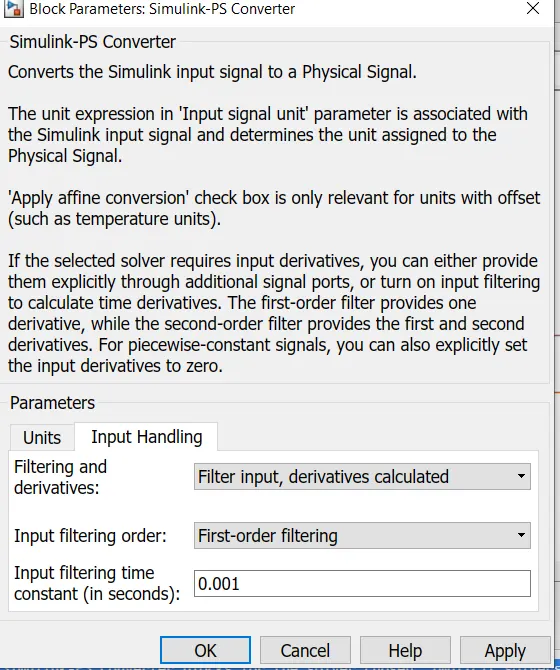
Error encountered
Solution for the error
changing the filter and derivatives to filter input and derivatives calulated
Result
output from the switch
time vs swith open/close
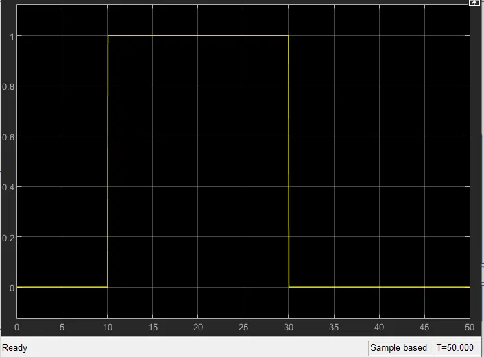
If the threshold value is equal to or greater than 0.01196 then the switch opens in the below plot the switch opens between 10 to 30 secs as the incoming signal value is greater than threshold value.
output of voltage sensor
voltage vs time
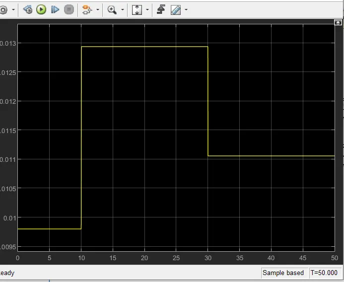
The current is directly proportional to the voltage and inversely proportional to the resistance. This means that increasing the voltage will cause the current to increase, while increasing the resistance will cause the current to decrease.
The above statement we can related it with the above graph, when the temperature increases the resistance decreases and there will be increase in current and voltage which is visible in graph above.
output of the fan
rpm vs time
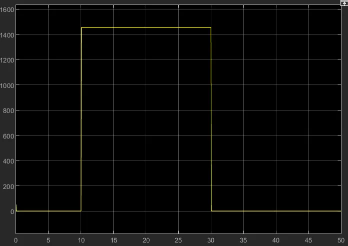
from the above graph we can see that the fan is turned on between 10 to 30 secs when the temperature is above 25 degree celsius.