Week -2
#1. Make a simulink model of doorbell using solenoid block with the following details
Create a situation where the switch is closed for 2 secs and then released. Observe the physical movement of the plunger.
Doorbell model:
The components required are
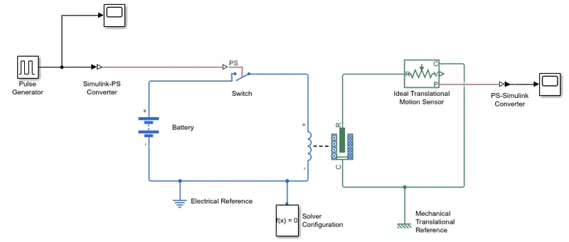
Signal generator: It is used to generate a square wave with total period of 4sec and amplitude of 1v.
Simulink PS-converter: It converts simulink input signal to physical signal.
Switch: It is controlled by external physical signal. When the physical signal becomes greater than threshold the switch closes otherwise it remains open.
Battery: It is used as a source with a voltage of 30v.
Solenoid: It is a device comprised of coil of wire, the housing and a movable plunger. When the current passes through the coil it creates magnetic field around the coil which makes the plunger to move. It is a devise which converts electrical energy into mechanical work.
Ideal translational sensor: It converts a variable measured between 2 mechanical translational nodes into a control signal proportional to velocity and position.
PS-simulink converter: it converts physical signal into simulink output signal.
And Electrical reference, Mechanical translational reference, solver configuration, scope.
Simulink model of doorbell:
Explanation:
Pulse generator is used to generate a square wave which is converted into physical signal and given as an input to switch. When physical signal becomes greater than threshold i.e above 0.8 the switch get closes it allows the current to flow through the coil of the solenoid which sets up a magnetic field around it which draws the plunger in.
This is monitored by ideal translational motion sensor which is connected to C and R terminals of the solenoid. Its output ports for velocity and position are V and P respectively. Its position output is given to scope to observe the physical movement of the plunger.
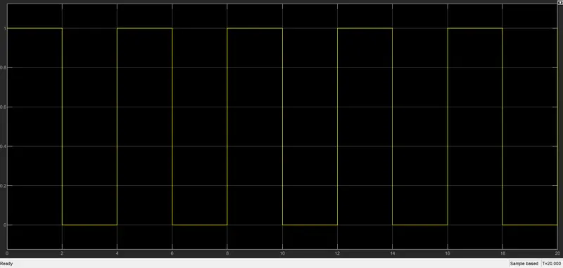
Input:
The plot shows the input signal (Amplitude=1, Period=4sec, pulse width=50%, Phase delay=0).
Output:
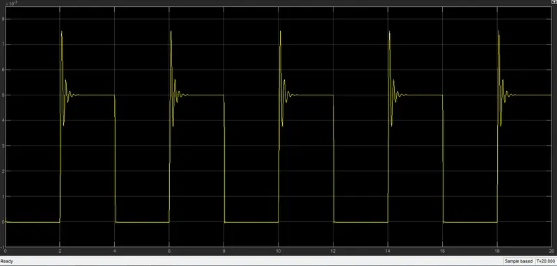
Thus as shown in the plot when the switch closes for 2 secs we can observe the physical movement of the plunger.
#2. Use a thermistor to sense the temperature of a heater and turn on or off the fan for below condition.
Temperature sourse: 20˚C from 0-10 sec, 27˚C from 10-30sec, 23˚C from 30-50 sec.
Fan condition: ON if the temperature above 25˚C, OFF otherwise.
Ans:
The blocks used in the model are
- Signal builder
- Simulink-PS converter
- Controlled temperature source
- Battery
- Thermistor
- Resistor
- Voltage sensor
- Switch
- PS-simulink converter
- Constant, display and scope
- Electrical reference, Mechanical reference and solver configuration.
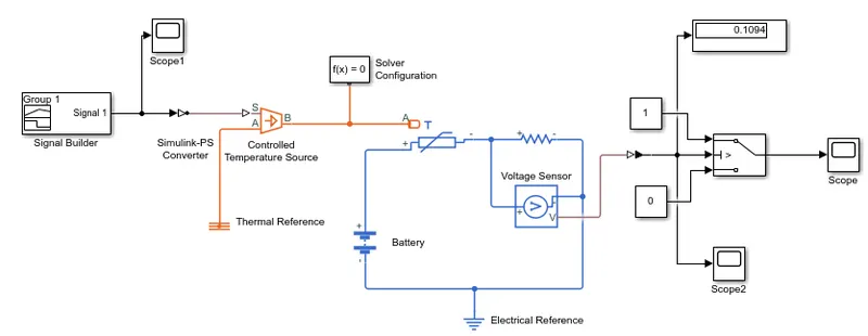
Explanation:
Since all the thermal blocks are in Kelvin in default ˚C is converted into Kelvin
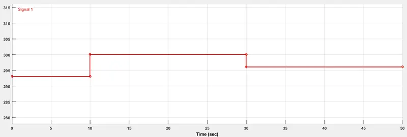
- Signal builder block is used to produce the input according to the condition 20˚C (293.15k) from 0-10 sec, 27˚C (300.15k) from 10-30sec, 23˚C (296.15k) from 30-50 sec.
- Input is converted into physical signal and connected to S terminal of the controlled temperature source.
- Controlled temperature source maintain a controlled temperature difference regardless of the heat flow rate. It output is connected to the thermal port A of thermistor.
- Thermistor is a resistor whose resistance is depends on temperature. It has 3 ports positive port, negative port which are connected to a battery through a resistor and thermal port.
- Battery is source which provides voltage of 12V DC.
- Resistor is connected in series with the thermistor to measure the variations in the model. If the resistance value changes then the Voltage drop across it also changes but once threshold value is mentioned in switch don’t change the resistance value. RTotal= RThermistor+ Rreference
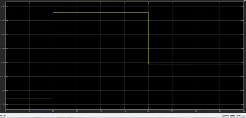
- Voltage sensor is connected in parallel with the resistor to measure the voltage drop across it.
- PS-simulink converter is used to convert physical signal of voltage into simulink output signal. which is connected to the control port of the switch.
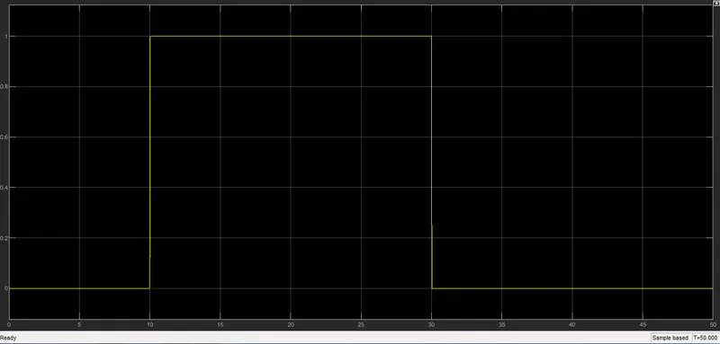
- Switch as 3 input ports 1 & 3 are data ports connected with constant block with a value of 1 & 0 respectively and 2 is the control port which is given with a threshold value of 0.127 when the input is greater than threshold it connects to 1 otherwise 0.
- Scope shows the output signal and display show numerical value.
Input:
Plot shows the input signal according to the condition 20˚C (293.15k) from 0-10 sec, 27˚C (300.15k) from 10-30sec, 23˚C (296.15k) from 30-50 sec.
The voltage sensor output is shown in the below plot
Output:
Result:
Hence by seeing the plot we can observe that, from 0-10 sec and 30-50 secs the fan is 'OFF' as temperature is less than 25˚C(300.15k) and from 10-30 secs the fan is 'ON' as temperature is greater than 25˚C(300.15k).