Week -2
Question 1:
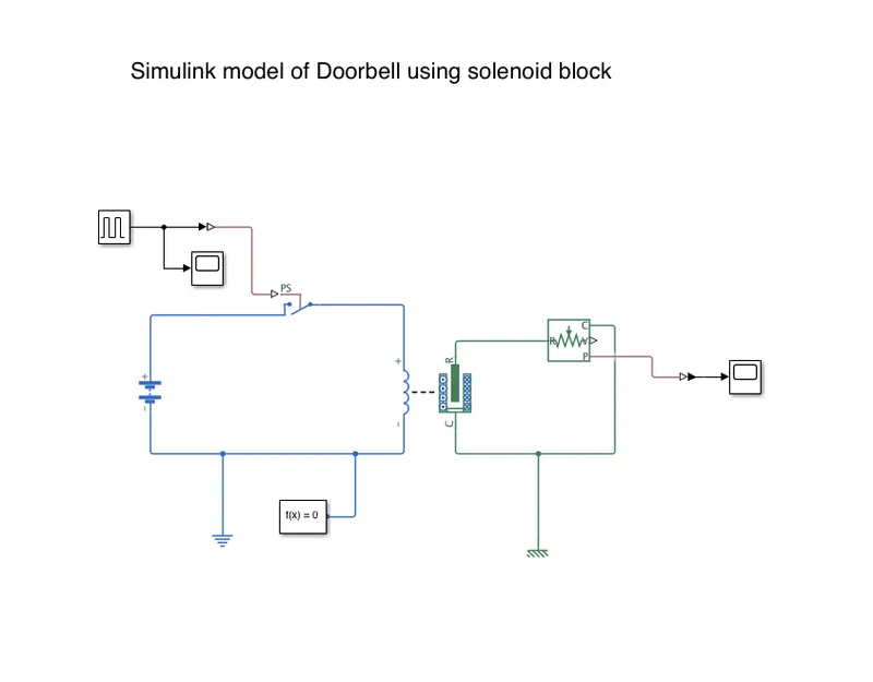
Make a Simulink model of Doorbell using solenoid block with the following details:
In the above arrangement, when the switch is closed the electromagnet receives electrical power from the battery and pulls the metal arm to hit the bell producing sound.
Create a situation where the switch is closed for 2 seconds and then released. Observe the physical movement of the plunger.
Assume remaining parameters.
Solution:
Aim
To Make a Simulink model of Doorbell using solenoid block.
Conditions
To Create a situation where the switch is closed for 2 seconds and then released.
To Observe the physical movement of the plunger.
Fundamental Simulink Blocks Required
1.Pulse Generator
The Pulse Generator is used to create square wave pulses at regular intervals.
2.Switch
This block represents a switch controlled by an external physical signal.
3.Battery
Battery is a storage device that provides the required voltage based on the parameter given. We can use DC voltage source blocks too.
4.Solenoid
This block implements the electrical and mechanical characteristics of a solenoid. A solenoid is a type of electromagnet, the purpose of which is to generate a controlled magnetic field through a coil wound into a tightly packed helix. The coil can be arranged to produce a uniform magnetic field in a volume of space when an electric signal is passed through it.
5.Ideal Translational Motion Sensor
This block measures velocity or displacement in a mechanical translational network.
6.Mechanical Translational Reference
This block represents a mechanical translational reference point, that is, a frame or a ground
7.Electrical Reference
These domain-specific electrical reference blocks will provide the required initial conditions to the connected thermal block for the solver.
8.Solver Configuration
The solver configuration block specifies the solver parameters that your model needs before you can begin simulation and this is mandatory for all simscape designs.
9.Scope
This is an output block that shows the signal with respective time in an X-axis.
Procedure
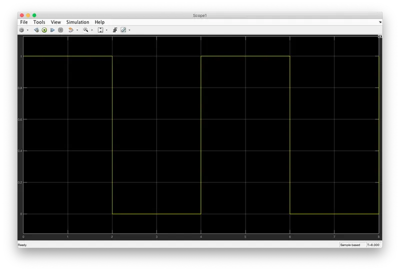
Pulse Generator produce the input signal of given condition by varying the parameter like period and pulse width. i.e period= 4 seconds, pulse width = 50%.
This will produce a signal which is ON for 2 seconds and OFF for 2 seconds. This input is given to the Switch through a Simulink to PS Converter.
A Battery is connected to the switch through a solenoid. An Ideal Translational Motion sensor is connected with the solenoid block to observe the physical movement of the plunger.
A Scope is connected with the ideal translational motion sensor to get the output.
Input
Pulse Generator Input
Output
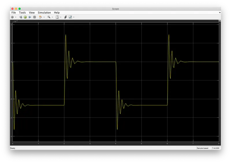
The below graph shows physical movement of the plunger when the switch is in ON and OFF conditions.
Result
From the Graph,
When the switch is closed, the solenoid block receives electrical power from the battery and the plunger moves from port R to port C to hit the bell and it produces sound.
Simulink Model
Question 2:
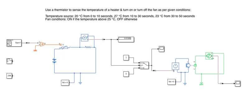
Use a thermistor to sense the temperature of a heater & turn on or turn off the fan as per below conditions:
Temperature source: 20 °C from 0 to 10 seconds, 27 °C from 10 to 30 seconds, 23 °C from 30 to 50 seconds
Fan conditions: ON if the temperature above 25 °C, OFF otherwise
Solution:
Aim
To Use a thermistor to sense the temperature of a heater & turn on or turn off the fan as per given conditions.
Conditions
Temperature source: 20 °C from 0 to 10 seconds, 27 °C from 10 to 30 seconds, 23 °C from 30 to 50 seconds
Fan conditions: ON if the temperature above 25 °C, OFF otherwise
Fundamental Simulink Blocks Required
1.Signal Builder
to generate the signal according to the input condition given.
2.Controlled temperature source (CTS)
provide a temperature physical output based on the condition given to port S.
3.Thermal Reference
This block provides the required initial conditions to the connected thermal block for the solver.
4.Thermistor
Thermistor block which shows us the NTC thermistor relation between temperature and resistance.
5.Battery
Battery is a storage device that provides the required voltage based on the parameter given. We can use DC voltage source blocks too.
6.Resistor
Resistor which provides the opposing nature of current in a circuit.
7.Voltage Sensor
This is used to measure the voltage or potential difference across any electrical component and it should connect in parallel only.
8.Electrical Reference
These domain-specific electrical reference blocks will provide the required initial conditions to the connected thermal block for the solver.
9.Solver Configuration
The solver configuration block specifies the solver parameters that your model needs before you can begin simulation and this is mandatory for all simscape designs.
10.Simulink-PS Converter
Converts simulink signals to the respective physical signal.
11.PS-Simulink Converter
Converts physical signals to the respective simulink signal.
12.Constant
provides a constant output value.
13.Switch
This block is used from the library Simulink/Signal Routing where it has three inputs namely Port1, Port2 and Port3. Port2 is a control input where the signal given to port2 is satisfied with the condition and threshold of the switch block then it passes Port1 as output and if it is not satisfied then it will pass Port3 as output.
14.Scope
This is an output block that shows the signal with respective time in an X-axis.
Procedure
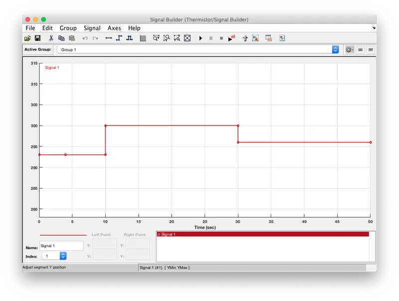
Signal builder produces signals of 20°C(293K), 27°C(300K) and 23°C(296K) with respect to t=0-10s, t=10-30s and t=30-50s.
These are the input signals given to controlled temperature source to attain the given conditions.
The Controlled temperatures source is connected to A terminal of the Thermistor. The Positive terminal of thermistor is connected to positive terminal of battery and negative terminal of thermistor is connected to the negative terminal of battery through a resistor.
A voltage sensor is connected parallel to the resistor to measure the threshold by giving the condition(25°C=298K) through a constant block. Afterthat, constant block is disconnected and signal builder is connected.
A switch is connected to the output of the voltage sensor to operate only if it satisfies the condition. A scope is connected to the output of the switch to see the result.
Also the DC Motor Setup is connected to the output of the Switch to see the results.
Input
Signal Builder Input
Output
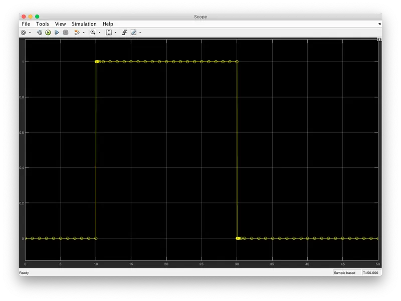
The below graph shows the output of the switch which operates at given conditions.
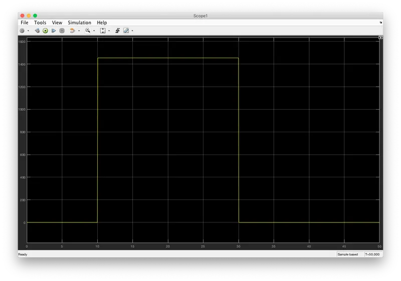
The below graph shows the output of the DC Motor through a Ideal Rotational Motion Sensor which operates at given conditions.
Result
From the Graph,
At t=0-10 seconds, fan is in OFF condition because temperature is 293K which is below the threshold 298K.
At t=10-30 seconds, temperature goes to 300K then the fan will be in ON condition as the temperature exceeds 298K.
At t=30-50 seconds, the fan will turn OFF as the temperature comes down to 296K which is below the threshold temperature of 298K.
Simulink Model