Week -2
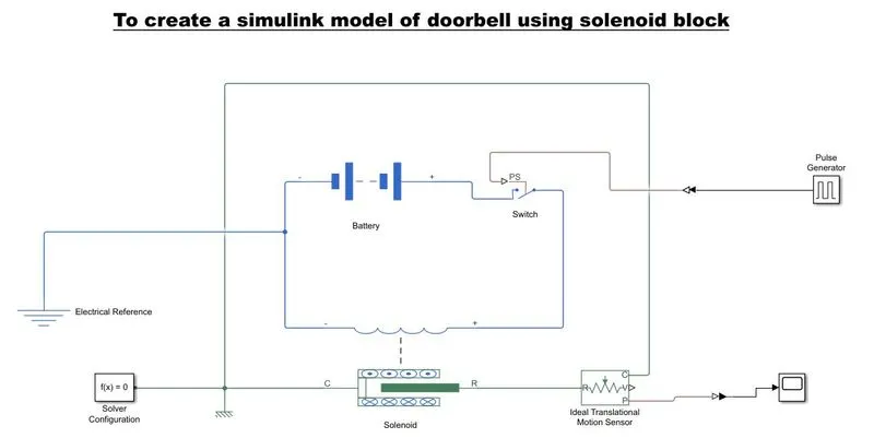
- Make a Simulink model of Doorbell using solenoid block with the following details:
) In the above arrangement, when the switch is closed the electromagnet receives electrical power from )the battery and pulls the metal arm to hit the bell producing sound.
Create a situation where the switch is closed for 2 seconds and then released. Observe the physical movement of the plunger.
Assume remaining parameters.
Blocks used:
1) Pulse Generator: The pulse generator block generates square wave pulses at regular intervals
2) Simulink-PS converter: It Converts the simulink input signal into Physical Signal
3) Switch: Switch controlled by an external physical signal
4) Battery: It gives the power to the closed loop
5) Electrical Reference: It shows Connection to electrical ground
6) Solenoid: Electrical characterstics and generated force of soleniod
7) Ideal translational Motion Sensor: It is a motion sensor in mechanical translational systems.
8) PS-Simulink Converter: It Converts physical signal into simulink output signal
9) Mechnical Translational References: Reference connection for mechanical translational ports.
10) Scope: It Display signals generated during simulation.
WORKING PRINCIPLE OF DOORBELL BY USING SOLENOID:
* The Switch is pressed and currents flows through the circuit
* The electromagnet is powered and generates a magnet field that attracts the iron strip towards it.
* The striker strikes the gong (bell)
* When the striking arm strikes the gong, the contact is broken and current stops flowing through the circuit.
* This causes the electromagnet to lose its magnetic field.
* The connected spring arm returns the striker to its original rest position
* The contact is restored and current flows through the circuit (provided the main switch is still pressed).
* The process is repeated from the the beginning.
STUDY EXPLANATION:
INPUT (PULSE GENERATOR)
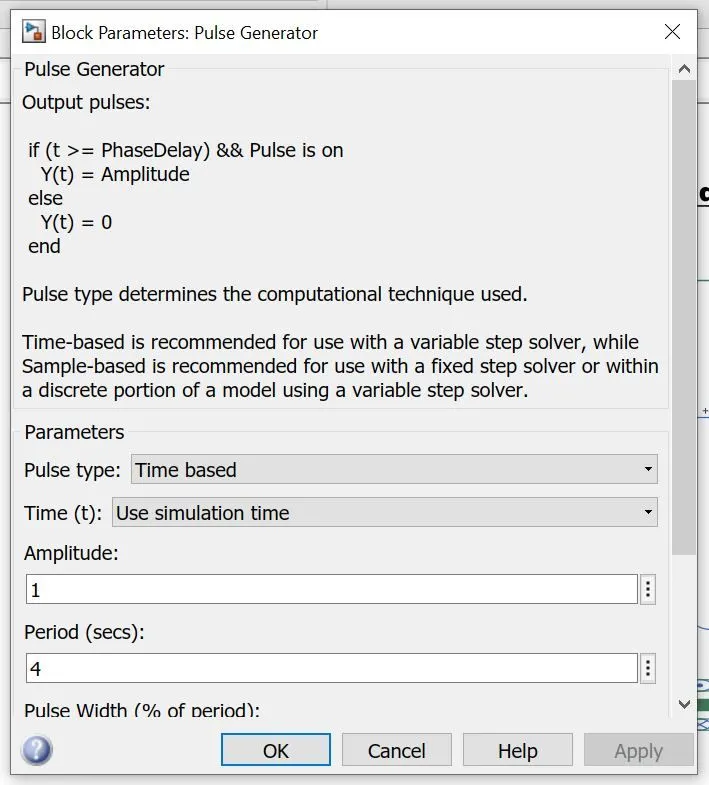
* To Create a circuit an input values are connected for power supply here pulse generator are used as input block. Scope1 were connected to pulse generator to execute graph of input.
* Simulink to PS converter connects the pulse generator and switch block. One end of switch is connected with battery and other with solenoid.
* The Solenoid block represents the electrical charcteristics and generated force fo the solenoid. It converts the electrical characterisctis to mechanical.
* Now the plunger in Solenoid are connected to ideal translational motion sensor The block represents an ideal mechanical translational motion sensor, that is, a device that converts sn across variable measured between two mechanical translational nodes into a control signal proportional to vellocity and position.
* A case mechanical in solenoid is connected to ideal translational motion by the refernce of mechanical translational the solver also connected in this circuit for execute circuit without error.
* An output from ideal translational motion sensor are connected with scope by using PS Simulink converter
* Display block shows resulant value of output in this condition it is not necessary to indicate that
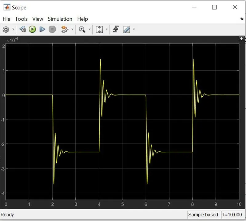
* Thus graph is obtained in scope block
OUTPUT:
CONCULSION:
1) Understanding the changes in the curve characteristics upon changing the solenoid parameters
2) Understanding the principle if working of a Doorbell and its construction
3) Analyzing the Various simulink Library blocks.
RESULT: In the above results the switch is closed the electromagnet receives electrical power from the battery and pulls the metal arm to hit the bell producing sound
* The motion of plunger was simulated and recorded and plotted by using and ideal motion sensor and scope.
Use a thermistor to sense the temperature of a heater & turn on or turn off the fan as per below conditions:
Temperature source: 20 °C from 0 to 10 seconds, 27 °C from 10 to 30 seconds, 23 °C from 30 to 50 seconds
Fan conditions: ON if the temperature above 25 °C, OFF otherwise
Solution:
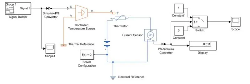
* Power supply like battery and current sensor is connected with thermistor.
* Signal builder gives inpur to controlled the temperature source.
* Output of controlled temperature is connected with thermistor
* Solver attempts to find the steady state that would result if the inputs to the system were held constant for a sufficently large time, starting from the initial state obtained from the initial conditions computation.
* From the sensor connection is given to the switch and two constants are added for detailed ouput,
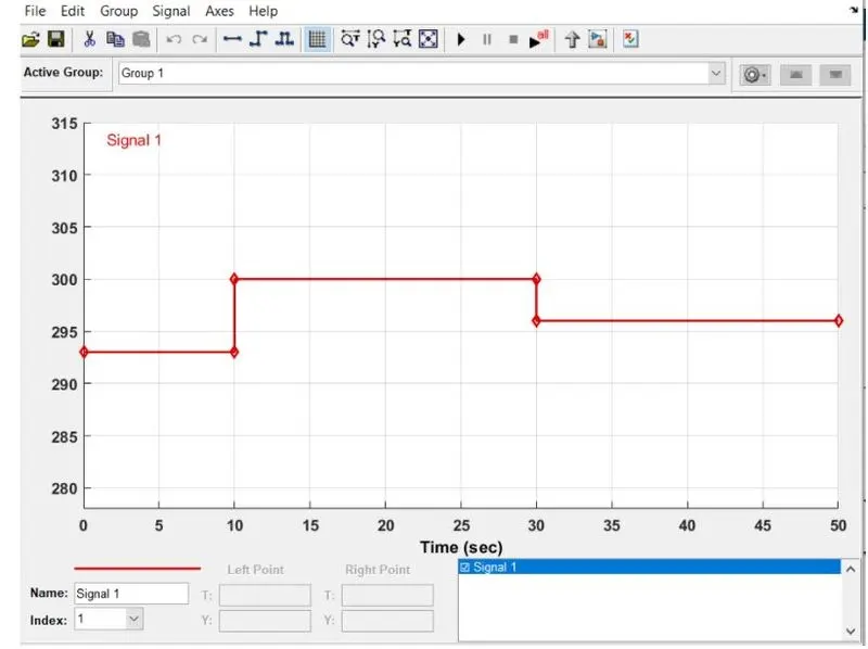
Result: Thus the thermistor is used to sense the temperature as per the given conditions and output is Obtained.