Week -2
`mew``permiability`AIM:-To simulate dorrbell and heater model using simulink.
OBJECTIVE:-
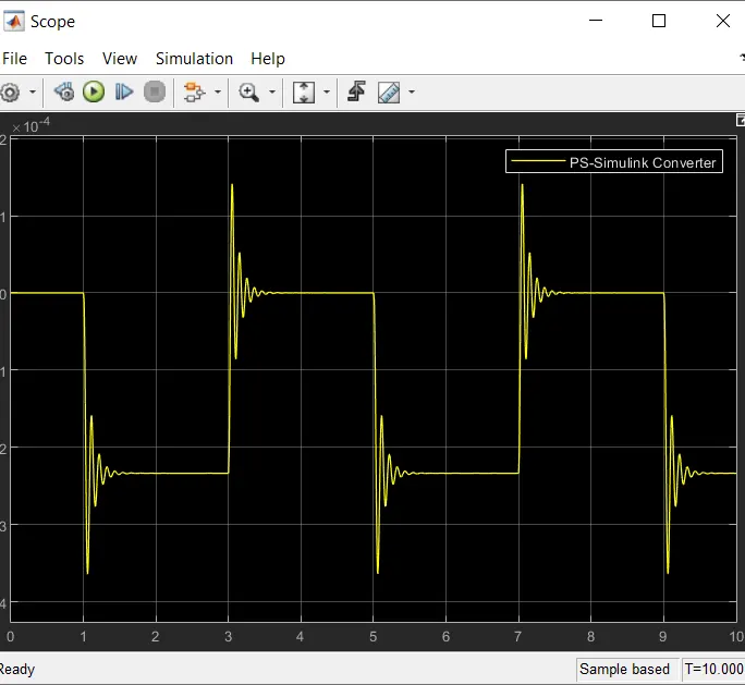
1.To observe the physical movement of the plunger by creating a situation ehrer the switch is closed for 2 seconds and then released.
2.To use a thermister to sense the temperature of a heater and turn on or turn off the fan as per below conditions:
Temperature sourse: 20'C from 0 to 10 seconds , 27' C from 10 to 30 seconds . 23' c from 30 to 50 seconds.
Fan condition:ON if the temperature above 25'C , OFF otherwise.
SOLUTION:
part-1:
THEORY:
Doorbell: The electric doorbell is a simple ciruit that triggers a sound on the completion of the circuit by pressing the button.
When the switch is pressed , the circuit loop is complete which causes the current to flow through the circuit. The arm which strikes the gong is connected to spring at one end and an iron ball at the other end . This is called a hammer or a striker . The arm is attached on an iron strip which is attracted to the electromagnet when when the circuit is complete and the current flowing through it.
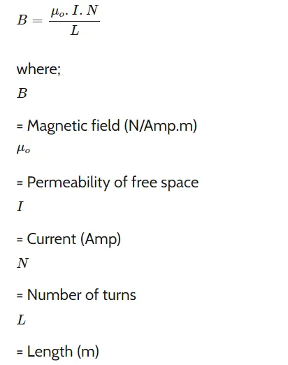
Solenoid:- A solenoid is a type of electromagnet , the purpose of which is to generate a controlled magnetic field through a coil wound into a tightly packed helix.T0he coil can be arranged to produce a uniform magnetic field in a volume of sace when an electric current is passed through it.
A solenoid is a coil of wire designed to create a strong magnetic field inside the coil.By wrapping the same wire many times around a cylinder , the magnetic field due to the wires can become quite strong. The number of turns N refers to the number of loops the solenoid has. More loops will bring about a stronger magnetic field.
The formula for the field inside the solenoid is:
EXPLANATION of the model:
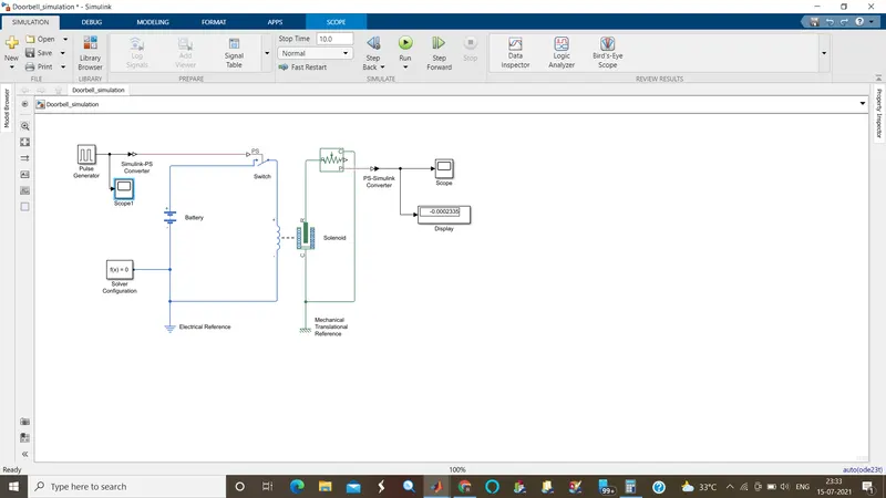
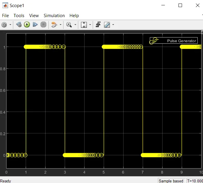
- An input signal is given according to given condition (Amplitude=1, Perid=4sec, PulseWidth=50%, Phasedelay-2sec).
- A simulink-PS converter is used to convert the input Simulink signal in to a physical signal.
- A switch is connected to battery and solenoid respectively as sown. If the external physical signal PS is greater than the threshold , then the switch is closed , otherwise , the switch is open.
- Solenoid converts electrical signal to mechanical signal.
- The ideal mechanical translational motion sensor converts an across variable measured between two mechanical translational nodes into a control signal proportional to velocity and position .
- A PS-Simulink Converter is used to convert the physical signal into a simulink output signal.
- The solver configuration block specifies the solver parameters that your model needs before you can begin the simulation.
- Finally ,Scope and Display are used to obtain the output plot.
A Simulink model for the plunger ovement according to given conditions is shown below.
INPUT SCOPE:
OUTPUT SCOPE:
 Part-2:
THEORY:
THERMISTER: A thermister / thermal resistor is defined as a type of resistor whose electrical resistance varies with changes in temperature changes.
There are two types pf thermistors:
- Negative temperature coefficient(NTC) thermistor.
- Positive temperature coefficient(PTC) thermistor.
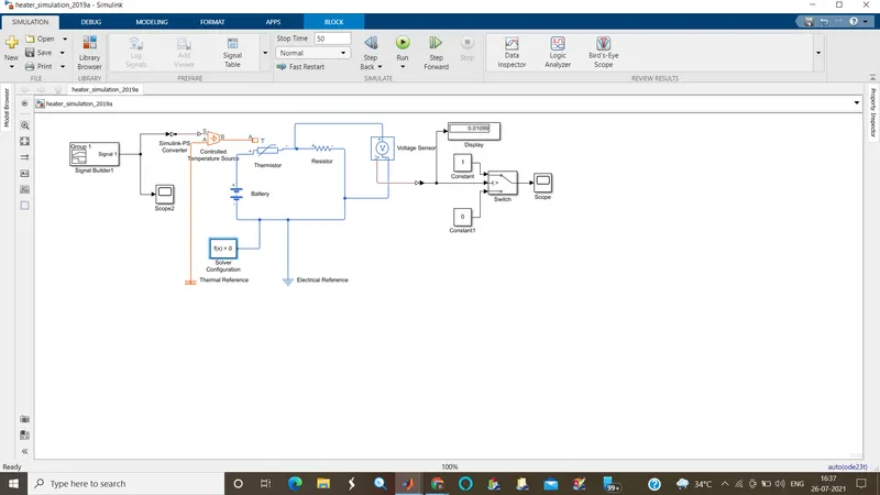
Explanation of the themistor simulink model:
- A signal builder is given according to given conditions (20 degree C from 0 to 10 seconds , 27 degree C from 10 to 30 seconds , 23 degree C from 30 to 50 seconds. FAN conditions: ON if the temperature above 25 degree C, OFF otherwise.
- A simulink-PS Converter is used to convert the input Simulink signal in to physical signal.
- Controlled Tenperature source is an ideal energy source in a thermal network that can maintain a controlled temperature difference regardless of the heat flow rate.
- Thermister is a resistor whose electrical resistance varies with changes in temperature.
- A voltage source of 12 V DC is given to the circuit.
- A refference resistor is used to meaasure the fluctuations in the model.
Total Resistance in series:

- A voltage sensor converts voltage measured between any electrical connections into a physical signal proportional to the voltage .
- A PS-Simulink Converter is used to convert the physical signal in to a Simulink output signal.
- The Threshold value obtained by the output of voltage sensor is used by the switch to display "1" and "0" using the if-else condition.
- The Solver Configuration blok specifies the solver parameters that your model needs before you can begin the simulation.
- Finally , Scope is used to obtain the output plot.
A Simulink model for temperature sensing and operating the fan according to given conditions are shown below.
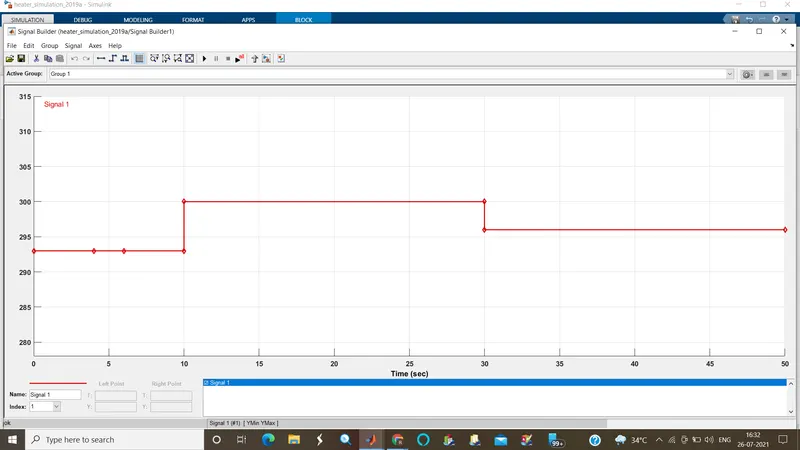
Input from the signal generator to the heater simulation model:
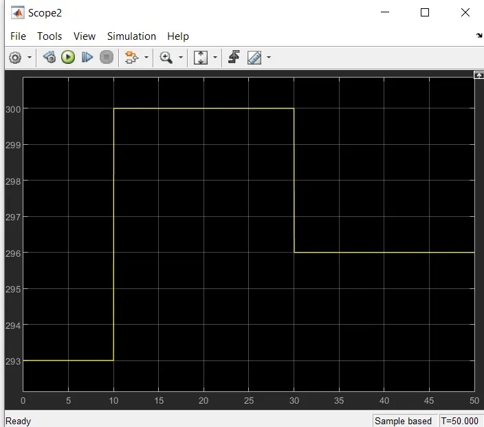
A plot is displayed below for 20 degree C (293 K) from 0 to 10 seconds , 27 degree C (300 K) from 10 to 30 seconds , 23 degree C(296 K) from 30 to 50 seconds.
A plot for the input scope is displayed below.
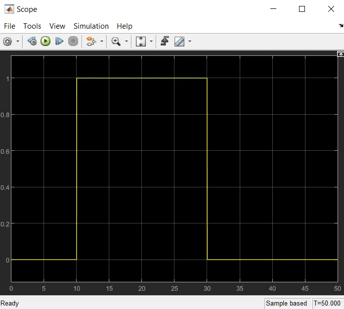
Output: For the first and last 20 sec , the fan is OFF as temperature is less than 25 degree C and for 20-30 sec , the fan is ON as temperature is greater than 25 degree C.
CONCLUSION:
Hence , the given problem was simulated according to the given conditions.
- The physical movement of the plunger was observed in the Doorbell model.
- Fan temperature was sensed by the thermistor in the Heator model.
REFERENCES:
- https://in.mathworks.com/matlabcentral/fileexchange/71881-magnetic-fields-of-solenoids-and-magnets?s_tid=srchtitle
- neeraj_wce (2021). Thermistor Model (https://www.mathworks.com/matlabcentral/fileexchange/59871-thermistor-model), MATLAB Central File Exchange.
- https://in.mathworks.com/matlabcentral/fileexchange/59871-thermistor-model?s_tid=srchtitle