Week -2
Solenoid:
A solenoid is a type of electromagnet which generates a controlled magnetic field through a coil wound into tightly packed helix. The coil can be arranged to produce a uniform mgnetic field in a volume of space when an electric current is pssed through it.
In electromagnets, a solenoid is an actuator assembly with a sliding ferromagnetic plunger inside the coil. Without power, the plunger extends for part of its length outside the coil; applying power pulls the plunger into the coil.
Thermistor:
A thermistor is a type of resistor whose resistance is dependent on temperature. Widely used as inrush current limiters, temperature sensors (negative temperature coefficient or NTC type typically), self resetting overcurrent protectors, and self-regulating heating elements (positive temperature coefficients or PTC type typically).
Thermistors are of two opposite fundamental types:
1. With NTC thermistors, resistance decreases as temperature rises. An NTC is commonly used as a temperature sensor, or in series with a circuit as an inrush current limiter.
2. With PTC thermistors, resistance decreases as temperature rises. Commonly installed in series with a circuit and used to protect against overcurrent conditions as resettable fuses.
Governing Diagram:
For electric bell:
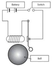
Basic Elements:
1) Battery
2) Switch
3) Solenoid
4) A bell with plunger
For Thermistor:
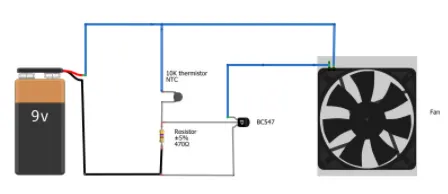
Basic elements:
1) Battery
2) Thermistor
3) Fan
4) Transistor
5) Resistor
Objective:
1) Create a situation where the switch is closed for 2 sec and then released. Observe the physical movement of the plunger.
2) Temperature source should be 20 degree celcius from 0-10 sec, 27 degree celcius from 10-30 sec and 23 degree celcius from 30-50 sec. Fan conditions should be ON if the temperature above 25 degree celcius, OFF otherwise.
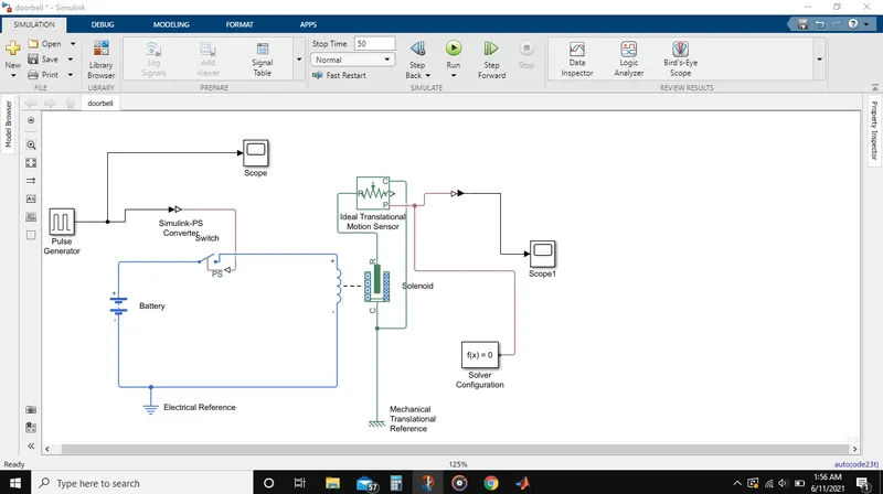
Steps involved in making the model:
1) Solenoid block is taken to represent a solenoid in the model, then to represent the battery we have taken battery block from the library browser.
2) Solenoid block is connected to the battery block via +ve and -ve terminals.
3) Switch is placed between solenoid and battery and is connected to both the blocks.
4) For the switch to operate we need to provide a physical signal through PS-port in the switch block and should be greater than the threshold of the switch, for switch being closed or else open.
5) The whole battery switch and solenoid path is connected to an 'electrical reference block' which represents earthing of the circuit. It should be connected to the -ve port of the battery block.
6) In solenoid block R and C are two variables which represent plunger and fixed point respectively. R is connected to the R of 'Ideal Motion Sensor block' which senses the position of the plunger and gives the output.
7) Ideal Motion sensor block the outputs are given as V and P which represent the velocity and position of the plunger. Since we are only interested in the position, we only need the output from P output.
8) C in the ideal translational motion sensor block is a mechanical translation conserving port, which means that the mechanical process starts from 'R' and ends at 'C' and then again it starts at 'R' and the cycle goes on.
9) So, C in Ideal motion sensor block is connected to mechanical translational reference which represents a fixed point where it is rigidly clamped in real time.
10) Similarly 'C' of solenoid block is also connected to the same 'Mehanical translational reference' as fixed point for the solenoid.
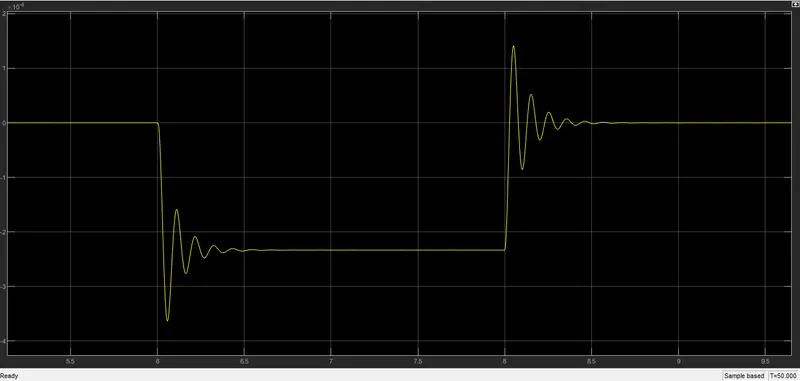
11) PS-Simulink converter is used to convert physical values from port 'P' are converted into simulink values and then this 'PS-Simulink Converter' is connected to scope block which will generate a graph for change in position of plunger from the port 'P' of 'Ideal Translational Moton Sensor Block'.
12) Pulse generator block is used to generate a continuous square pulse.
Pulse Generator Scope:
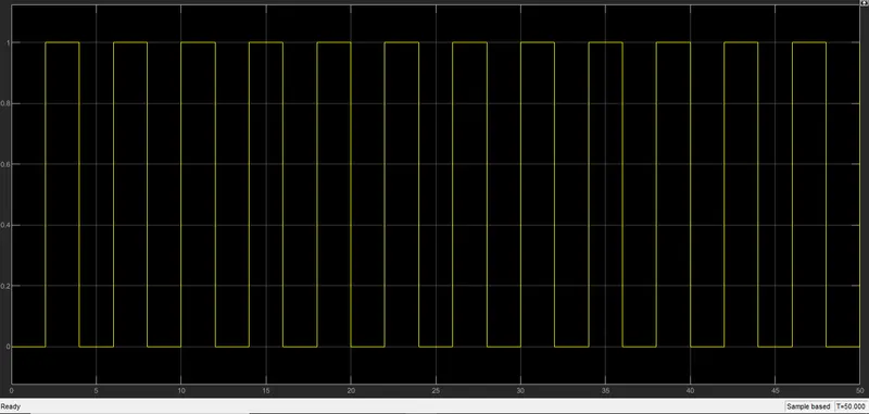
Ideal Translational Motion Sensor Scope Result:
II
For Thermistor operating Fan:
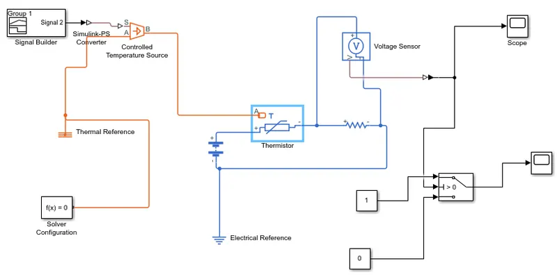
Basic Component:
i) Thermistor
ii) Battery
iii) Resistor
iv) Voltmeter
v) logical switch
PROCEDURE:
1) Positive of battery is connected to the positive of thermistor.
2) Positive of resistor block is connected to the negative of battery block and an electrical referernce is connected to the negative terminal of the battery.
3) Voltage sensor block is connected parallel to the resistor block.
4) We need a physical quantity for the thermistor to work, herre we need fan to get ON and OFF at different tempertures.So to provide temperature we have used 'Controlled Temperature Source Block' which only gives a specified temperature as output even though heat flow is more.
5) To give temperature to the 'Controlled Temperature block' we need to end temperature signals. Signal builder block is used to sendany type of signals as input.
6) Setting the signals and units according to our requirement.
SCOPE OF SIGNAL BUILDER BLOCK:
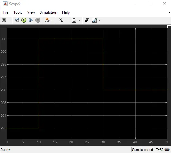
7) The signal from signal builder block needs to be converted to physical system signals.
8) Port B of Controlled Temperature Source Block is connected to port A of the thermistor block and port A of controlled temperature Souce block is connected to the thermal reference. In controlled temperature Source block a positive temperature difference causes the temperature at port B to be greater than the temperature at port A.
9) Output of voltage sensor block is connected to the scope via PS-Simulink converter.
SCOPE FOR VOLTAGE SENSOR BLOCK:
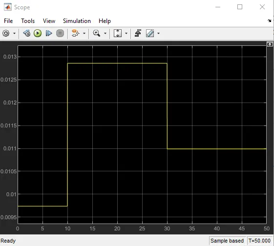
10) In the graph we can see that from time 0-10 sec when temperature is 293 K, voltage is between 0.0095 and 0.01 and from time 10-30 sec when temp is 300K voltage is between 0.0125 and 0.013 and from 30-50 sec when temperature is 296K voltage is nearly 0.012.
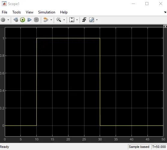
11) As mentioned in the objective fan should be on when temperature more than 25 degree celcius, from the above graph when voltage is more than 0.012 thefan should be on and when below 0.012 fan should be off.
12) From above logic we create a switch that routes the signal according to the condition required.
13) The centrre port of the switch block is thecondition input which means that when the value from the voltage sensor block is more than the threshold value in the switch block then it will pass the value 1 which we have specefied at the top of the switch block. If less than the threshold value then it will pass value 0.
CONCLUSION:
From the above graph we can see that fan is ON only when the temperature is 300K and at remaining temperatures it is OFF.