Week -2
Objectives:
1.To design a Simulink model for a doorbell
- To design a Simulink model for a heater with thermistor to sense the temperature and the fan should on/off when the temperature is >25oC.
Objective1:
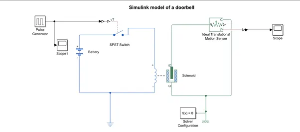
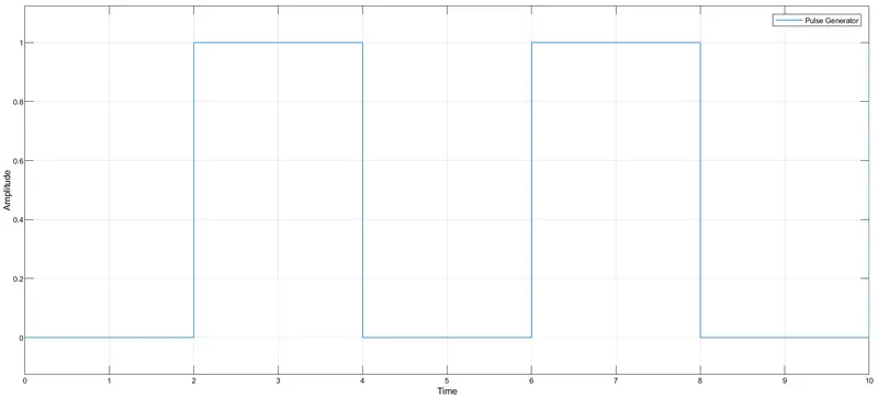
The doorbell model to be designed basically have a pulse generator, a switch (STSP switch), a battery, a solenoid, an ideal translational motion sensor as its building blocks. The mentioned blocks are connected accordingly to give the desired model shown in the model diagram. The pulse generator generates a signal in such a way that the bell rings for every 2 secs i.e. the period of the signal is 4 secs, pulse width would be 50% of period and the pulse delay is specified as 2 secs to meet the specifications of the objective. The solenoid here is energized with a battery and an SPST switch is connected in between the two. The output from the pulse generator is given to this through Simulink-PS converter. The output of the solenoid is given to an ideal translational motion sensor from which the output can be realized from the scope connected to it.
Input :
Output:
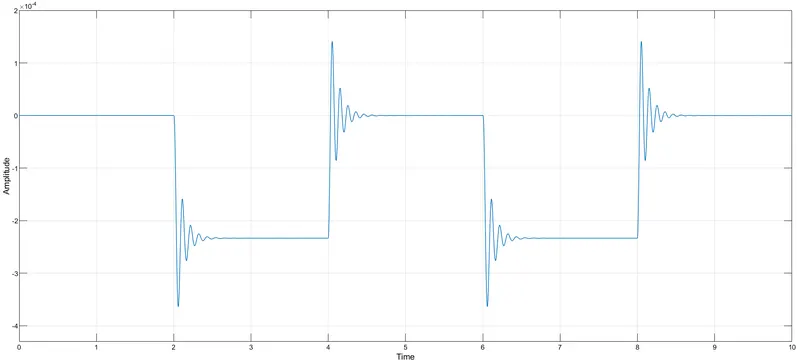
The distortions can be reduced by changing the damping of the solenoid and undistorted wave can be observed by increasing the damping value.
Results:
Hence, from the output it is realized that for every 2 secs, the switch will be closed and open. When the switch is closed, the solenoid receives the electric supply from the battery and the plunger of solenoid move from R to C to ring the bell and make sound.
Objective 2:
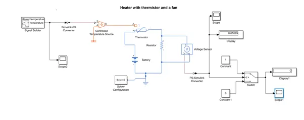
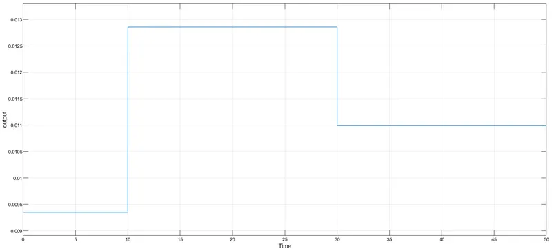
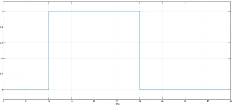
In the heater model, a thermistor is used to sense the temperature. When the temperature is more than 25oC, the fan should be switched on and for that a switch is used. The system would require a varied temperature as input to realize whether the system is in action or not. So a different signal containing 2-3 conditions with temperatures less than and more than 25oC. For such a typical signal, a signal builder is used. This signal is now fed to thermistor through Controlled temperature source. The thermistor is supplied with a battery of 12V and a resistor is connected in series to it. A voltage sensor is connected across the resistor to sense the voltage across the resistor. This voltage changes with temperature accordingly. The output from this can realized from scope through PS-Simulink converter. The output from this PS-Simulink converter is given to a fan which is to be controlled. This fan should ON/OFF when the temperature is more than or less than 25oC respectively. This can be seen in the scope connected to it. The model diagram of the system is as shown below.
Input:
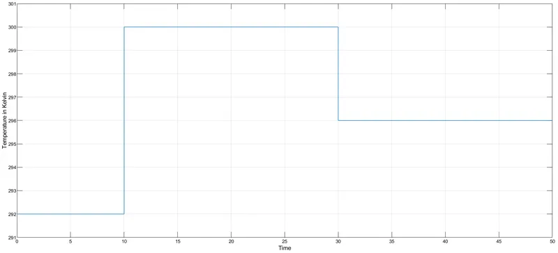
- From 0-10 secs, 292k or 18.85oC
- From 10-30 secs, 300k or 26.85oC
- From 30-50 secs, 296k or 22.85oC
Output:
Results:
From the above output waveforms,it is clear that during 10-30 secs, when the temperature is > 25oC, the fan is ON indicated by 1 as the amplitude of the waveform as rest is 0 where the temperature is <25oC.