Project
AIM:
- To simulate the BAJA ATV model.
- To explain the vehicle parameters.
- To show the final results.
OBJECTIVES:
- To simulate the ATV model with and without dashboard without look up table.
- To simulate the ATV model with and without dashboard with look up table.
Theory:
The BAJA ATV model i.e., an All-Terrain Vehicle refers to a single seater motor vehicle which runs on all kinds of terrains. This vehicle can run on both on-road and off-road terrains and this is because the tires of this vehicle are made of low pressure which are deep threaded. This facilitates the vehicle to run on rocky and mud terrains. These are customized for high performance racings, industrial applications, for defence purposes and also in agricultural needs. These have rigid structures and as they are off-road vehicles, they ensure the rider safety.
ATVs use CVT which refers to Continuous Variable Transmission. This helps the engine of ATV to run with constant RPM even if the vehicle run with variable speeds. CVTs are used in different vehicles such as cars, mopeds, tractors, ATVs etc.
OBJECTIVES:
Objective 1: To simulate the ATV model with and without dashboard without look up table.
Part 1: ATV model without dashboard and without lookup table:
The Simulink model for the ATV with no dashboard and lookup table is as shown below:
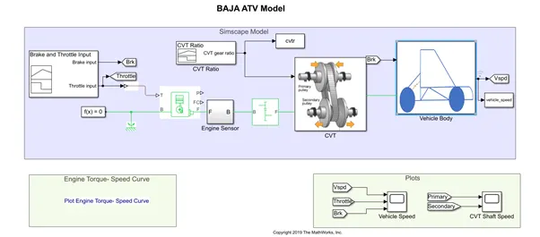
From the above model, it can be observed that a signal builder block is used. The brake (Brk) and Throttle signals are defined from the signal builder block. The throttle signal is given to the Generic engine block which here represents the engine of the model. Linear signals are given to the block as required in the model. The input signals are as shown below:
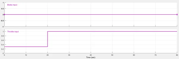
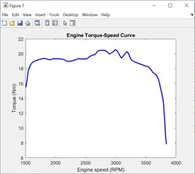
Here, Brake is not applied i.e., the signal is at zero. The throttle input is given such that it is at 0.3 for first 20 secs and it is at 1 for rest of the time.The throttle signal is given to terminal T of the generic engine block which is the throttle input to the engine. The ports B and F are the mechanical conserving ports associated with the engine crankshaft and engine block. The output from this is given to engine sensor block through F port of engine block. The engine is configured with “speed vector” and “Torque vector” externally through a mat file which gives real time data from an actual vehicle.
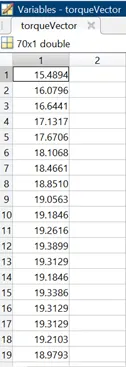
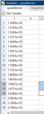
For engine block parameters, the settings were made such that by default the data is to be captured from the two blocks which are given the unit of RPM and N*m. The B port is connected to the mechanical reference and a solver configuration block is also connected. The F block is connected to engine sensor block which is built with RPM sensor to sense the RPM of the engine from the output shaft of the engine.
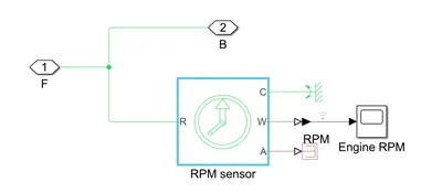
From the engine sensor, the output from RPM sensor is connected to CVT through a simple gear.
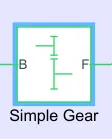
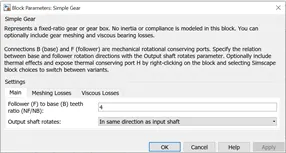
The simple gear block is nothing but a fixed gear box or simply a gear box whose gear ratio is fixed as 4 here. This is to get a proper speed at the output.
The RPM sensor basically senses the speed of the engine through its shaft. The port C is connected to the rotational reference. The output port F of engine sensor is connected to the input port of the CVT. The CVT is fed with a CVT gear ratio from a signal builder block. The output of the CVT gear ratio signal builder is as shown below:

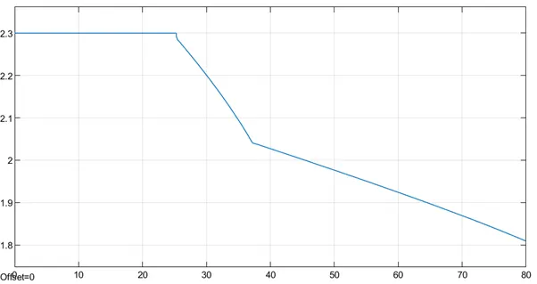
Here, the CVT gear ratio is maintained at 3.5 for the first 4 secs. This is then gradually decreased and settled at 0.5 from 35 secs to 80 secs. The CVT block built is as shown below:
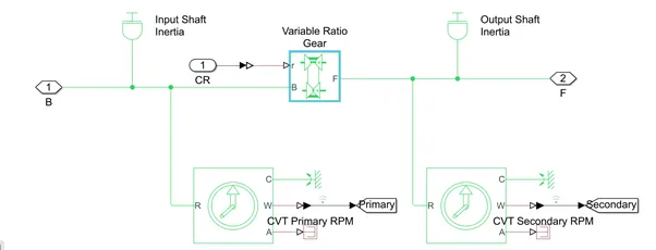
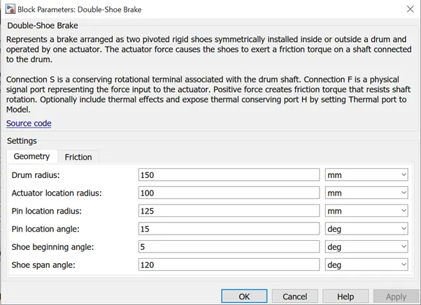
Here the input B port from simple gear block and CR block input from the CVT gear ratio block. There are two rotational sensors from the primary and the secondary transmission shafts which is input and output shaft of the transmission. The variable ratio gear block is added between the two rotational shafts i.e., rotational sensors which are the CVT transmission i.e., the variable ratio transmission implemented by mechanical belt CVT hydraulic or electric transmissions. Here the input port r defines the ratio of input to output angular shaft velocities, which is connected to the gear ratio and the port B is connected to the signal coming from the simple gear which is the input shaft. The port F is the output shaft port which then goes to connect to the body of the vehicle in the block diagram. The input and the output CVT shafts are also given an output that are then connected to the scope to view the RPM of these shafts. The Simulink brake input is connected to the Simscape double shoe brake via Simulink-PS converter and the parameters of the brake can be as shown below:
The output of the CVT is given as input to the vehicle body subsystem. The vehicle body block as seen below represents a two-axle body in longitudinal motion. The block consists of body weight, aerodynamic drag, weight distribution between axles due to acceleration and road profile and road incline.
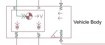
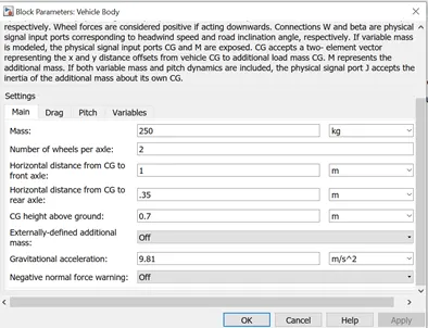
Wheel forces are considered positive if acting downwards. Connections W and beta are physical signal input ports corresponding to headwind speed and road inclination angle, respectively. The vehicle body block parameters can be seen below:
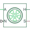
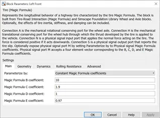
Connection H is the mechanical translational conserving port for the wheel hub through which the thrust developed by the tire is applied on the vehicle. Connection N is a physical signal input port that applies the normal force acting on the tire. The block parameters for the tire are as shown below:
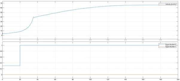
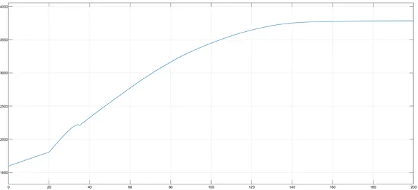
As per the input, the configuration is set to run for 80 secs. The simulation output is as shown below:
Vehicle speed:
Engine RPM:
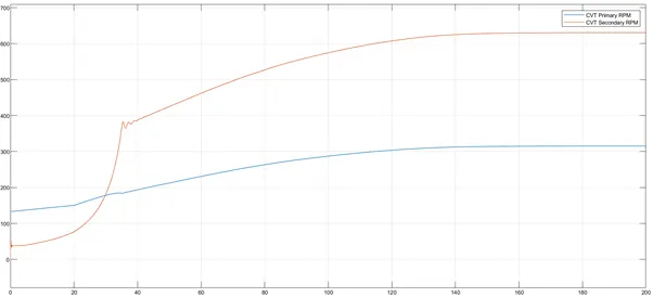
Primary and secondary CVT Shaft Speed:
Part 2: ATV model with dashboard and without lookup table:
The Simulink model of ATV with dashboard and without lookup table is as shown below:
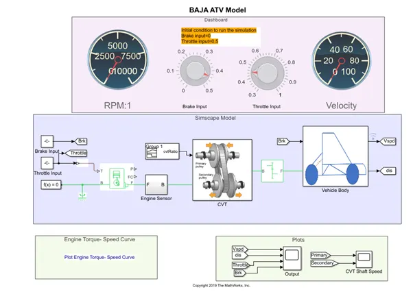
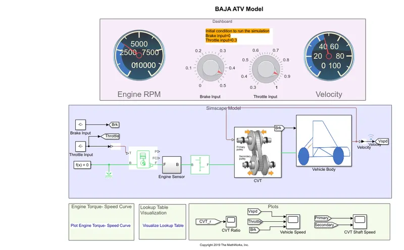
In this case a Simscape model was built with a dashboard similar to the vehicle. The rest of the model is same as the previous case. The only difference is that we can change the throttle and brake inputs manually with the help of the knobs provided on the dashboard of the model and outputs can be realized. This facility of changing the throttle and brake inputs is not available in the previous case. For this, the run time is to be changed to infinite and during run the knobs are moved and inputs are changed which affects the output also. The simulation can be stopped whenever we want manually using the “stop” button available beside the run.
The initial conditions to run the simulation were displayed on the dashboard and for the first time we run the simulation using the initial conditions.
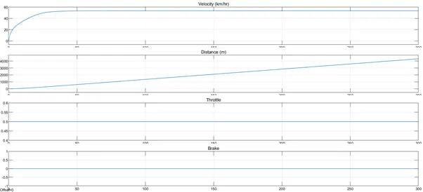
Outputs with the initial conditions:
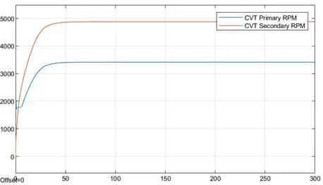
Primary and secondary CVT speed:
Engine RPM:
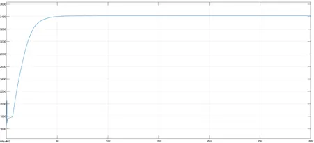
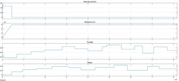
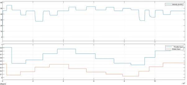
The brake and throttle inputs are changed manually using the knobs on the dashboard and the results are as follows:
CVT Shaft speed:
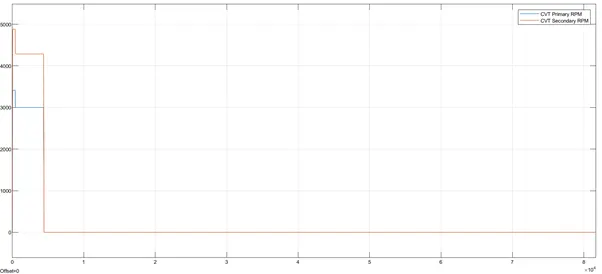
Hence the difference in throttle input and brake input results in the changes in the output as shown above.
OBJECTIVE 2: To simulate the ATV model with and without dashboard with look up table.
Part 1: ATV model without dashboard and with look up table:
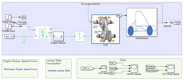
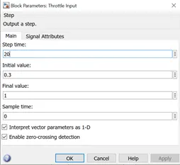
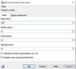
The main difference between the previous case where there is no lookup table and this is the CVT transmission ratio. In the earlier case, the input to the CVT is given by a signal builder block whereas, the present model has a lookup table predefined in the workspace and is linked to matlab externally via .mat file. The throttle and brake inputs are given from step inputs instead of a signal builder. The throttle and brake input block parameters are as shown below:
Throttle input block parameters:
Brake input block parameters:
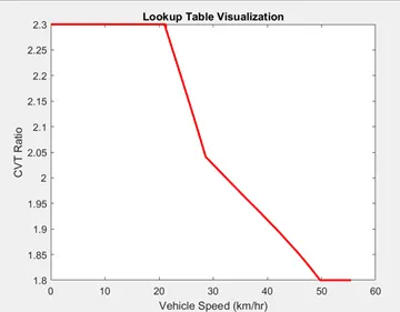
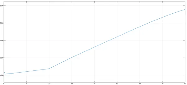
The lookup table is linked to the matlab externally using .mat file. To visualize the lookup table, use “Visualize Lookup Table” option and view it as shown below:
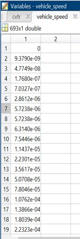
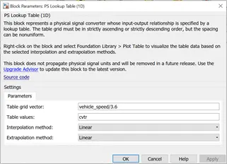
The lookup table file can be found in the workspace. The values of “cvtr” and “vehicle_speed” are fetched and those values are as shown below:
The transmission model with lookup table is as shown below:
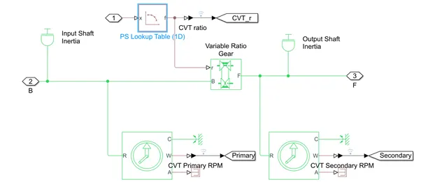
The lookup table block parameters are as shown below:
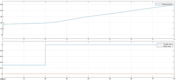
The model designed is simulated for 80 secs and the following plots were observed:
Vehicle Speed scope output:
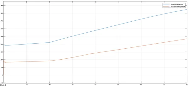
CVT Shaft output:
RMS Scope output:
CVT Ratio output:
Part 2: ATV model with lookup table and with dashboard:
The ATV model with dashboard is as shown below:
Vehicle speed scope output:
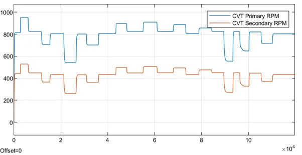
CVT Shaft scope output:
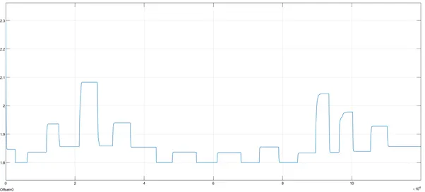
CVT Ratio Scope output:
Engine RPM:
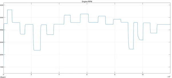
Hence, this is the case where the throttle and brake inputs are given externally using a lookup table and as the speed increases, the transmission ratio is decreasing. As the speed decreases, the transmission ratio increases.
Conclusions:
The four models i.e., the ATV model without lookup table and with lookup table which inturn have 2 cases with and without dashboard are studied and results are shown.